the12volt.com spacer
icon

viper 5704v and dball


Post ReplyPost New Topic
< Prev Topic Next Topic >
kreg357 
Platinum - Posts: 7,827
Platinum spaceThis member has made a donation to the12volt.com. Click here for more info.spaceThis member has been recognized as an authority in Electrical Theory. Click here for more info.spaceThis member has been recognized as an authority in Mobile Security and Convenience. Click here for more info.spacespace
Joined: January 30, 2009
Location: Pennsylvania, United States
Posted: August 07, 2013 at 10:23 PM / IP Logged  
The Brown Defrost wire is listed as (-). Set you DMM to 20V DC, connect the Red test lead to +12V constant and the Black
test lead to the Brown suspect wire. Start the engine and turn on the defroster. The DMM will either pulse a brief +12V
or the DMM will show a constant +12V. Set the Viper accordingly. Pretty sure it will be a constant / latched signal.
Do not combine the wires because the one single wire will not be able to supply the amps right?
Correct. Each Viper H3 power wire is rated at 30 Amps.
Don't think the prox sensor will be drawing a whole lot of amps, especially when the engine is remote started. You should
be OK running everything to the White wire. Finding space for four separate solder connections along a few inches of the
White wire shouldn't be an issue. Running a large gauge fused wire from the battery thru the firewall and making the Viper's
connections inside the Civic is another possibility.
Soldering is fun!
civicjunkie 
Member - Posts: 12
Member spacespace
Joined: May 01, 2013
Location: Ontario, Canada
Posted: August 09, 2013 at 7:24 PM / IP Logged  
one more stupid question:
the wiring harness for the two items D-BALL and Viper are 4000 feet long. Can i cut them and shorten them to bring the two closer together or will it affect anything due to Independence changes in the wires??
kreg357 
Platinum - Posts: 7,827
Platinum spaceThis member has made a donation to the12volt.com. Click here for more info.spaceThis member has been recognized as an authority in Electrical Theory. Click here for more info.spaceThis member has been recognized as an authority in Mobile Security and Convenience. Click here for more info.spacespace
Joined: January 30, 2009
Location: Pennsylvania, United States
Posted: August 10, 2013 at 4:28 AM / IP Logged  
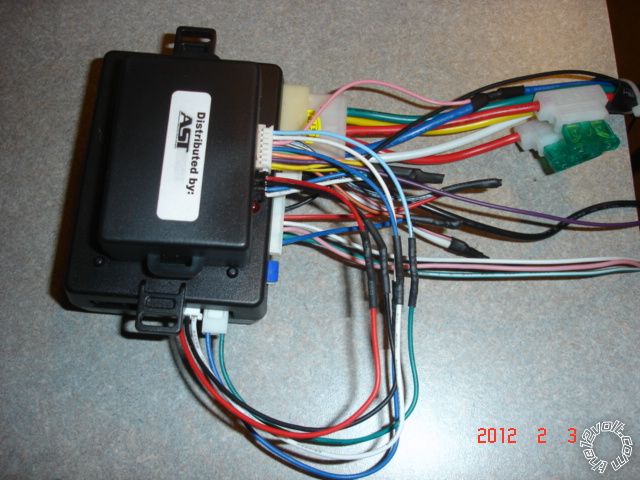
Yep, cut to length. There will be no issues with impedance due to wire length. Best practice is to "bench prep" the two modules by mating them on the bench, under ideal conditions, prior to install. As shown below, cut to length, solder & heat shrink all the necessary inter-connections. Then neaten and secure the wires. The wires that go to the vehicle can be neatly bundled in groups according to their final destination.
viper 5704v and dball - Page 2 -- posted image.
Soldering is fun!
civicjunkie 
Member - Posts: 12
Member spacespace
Joined: May 01, 2013
Location: Ontario, Canada
Posted: August 13, 2013 at 8:43 PM / IP Logged  
I have all my bench wiring done. I am confused with the shock sensor. The wire harness for it will fit in the viper or the D-BALL. I am assuming it goes into the viper but i want to be sure. Also the green wire on the harness is looped back on itself at one end and the other end is not attached to anything. The back of the shock sensor indicates the green wire is warn (-) output. So my question is what do i do with the unattached end of the green wire and which end of the harness (the looped, or single green wire end) do i attach to the viper and which to the D-BALL?
civicjunkie 
Member - Posts: 12
Member spacespace
Joined: May 01, 2013
Location: Ontario, Canada
Posted: September 26, 2013 at 10:48 AM / IP Logged  
can anyone help me wrap this up??
1) instructions say to use 7 pin immobilizer connector pin 3 lt grn immo data and pin 4 pink sw can. Problem is pin 4 is not pink its like a beige color. im not trying to be fussy but there is another wire in that connector that is clearly pink. what do i do
also reading on here i read that connector is suppose to be lime green but its white in my car. do i have the wrong connector
2) instructions say to use 18 pin plug above driver kick pin 16 grn lock and pin 12 gray unlock but reading on here it says to use pin 27 and 28 of 34 pin connector. which is better to use?
trying to get this done today please help
kreg357 
Platinum - Posts: 7,827
Platinum spaceThis member has made a donation to the12volt.com. Click here for more info.spaceThis member has been recognized as an authority in Electrical Theory. Click here for more info.spaceThis member has been recognized as an authority in Mobile Security and Convenience. Click here for more info.spacespace
Joined: January 30, 2009
Location: Pennsylvania, United States
Posted: September 26, 2013 at 7:46 PM / IP Logged  
Here is more info from iDatalink & Fortin on the 2008 Civic transponder plug :
Ignition       White 7 pin plug       Pin 2   Yellow (+)
Key Data    White 7 pin plug       Pin 3   Light Green (DATA)
SWC White 7 pin plug       Pin 4   Pink (DATA)
Look for that color sequence on the 7 Pin transponder connector. The wire at Pin 4 can look slightly
Orange to Beige. ( The one in the Civic Pictorial looks somewhat Orange.) Either way use the wire at
Pin 4.
The lock wires are the same at either location so use whichever one is easiest for you to make your
connections. The 34 Pin plug is found at the backside of the fuse box ( side towards the engine ).
Soldering is fun!
civicjunkie 
Member - Posts: 12
Member spacespace
Joined: May 01, 2013
Location: Ontario, Canada
Posted: September 26, 2013 at 8:54 PM / IP Logged  
Thank you kreg357! you are a life saver! now the yellow ignition wire in pin 2 of the 7 pin plug is not the yellow ignition wire that i am cutting for the ignition output and input right?? that yellow wire i will be cutting and using will be from the connector with the larger gauge wire right??
kreg357 
Platinum - Posts: 7,827
Platinum spaceThis member has made a donation to the12volt.com. Click here for more info.spaceThis member has been recognized as an authority in Electrical Theory. Click here for more info.spaceThis member has been recognized as an authority in Mobile Security and Convenience. Click here for more info.spacespace
Joined: January 30, 2009
Location: Pennsylvania, United States
Posted: September 26, 2013 at 9:22 PM / IP Logged  
Correct. This small yellow wire is an Ignition wire, not a Starter wire. Use the thick Yellow Starter wire on the main ignition connector / harness for your H3/4 and H3/5 connections.
Soldering is fun!
civicjunkie 
Member - Posts: 12
Member spacespace
Joined: May 01, 2013
Location: Ontario, Canada
Posted: October 17, 2013 at 5:36 PM / IP Logged  
kreg357 wrote:
Correct. This small yellow wire is an Ignition wire, not a Starter wire. Use the thick Yellow Starter wire on the main ignition connector / harness for your H3/4 and H3/5 connections.
Kreg357 i hope you are still around. Everything works with the viper but the remote start! When i try to remote start the park lights flash 7 times. The install guide Says "7 flashes - manual transmission mode is enabled and not initialized"
Also when i perform the shutdown diagnostics i also get 7 flashes from the control center it says "7 flashes - Timer mode/Turbo mode/Manual mode error"
What am i doing wrong??
civicjunkie 
Member - Posts: 12
Member spacespace
Joined: May 01, 2013
Location: Ontario, Canada
Posted: October 17, 2013 at 6:14 PM / IP Logged  
nevermind did some digging around and got it figured out. read that i would have to initialize it every time so put it in auto mode Thanks so much for your help
one question, i have my parking lights hooked up to the switch at the steering column. when i use the viper fob i notice it causes the light on the dash to illuminate for a brief moment indicating the lights are on. I seen somewhere that a remote start was installed (in the same car as mine)and a red wire down near the driver kick was used for parking lights. if i used this instead would it still cause the indicator on the dash to come on still??
Page of 3

  Printable version Printable version Post ReplyPost New Topic
You cannot post new topics in this forum
You cannot reply to topics in this forum
You cannot delete your posts in this forum
You cannot edit your posts in this forum
You cannot create polls in this forum
You cannot vote in polls in this forum

  •  
Search the12volt.com
Follow the12volt.com Follow the12volt.com on Facebook
Sunday, June 29, 2025 • Copyright © 1999-2025 the12volt.com, All Rights Reserved Privacy Policy & Use of Cookies
Disclaimer: *All information on this site ( the12volt.com ) is provided "as is" without any warranty of any kind, either expressed or implied, including but not limited to fitness for a particular use. Any user assumes the entire risk as to the accuracy and use of this information. Please verify all wire colors and diagrams before applying any information.

Secured by Sectigo
the12volt.com spacer
Support the12volt.com
Top
the12volt.com spacer