the12volt.com spacer
icon

viper 5704 d2d in 06 escalade ext


Post ReplyPost New Topic
< Prev Topic Next Topic >
trkle 
Member - Posts: 12
Member spacespace
Joined: September 17, 2013
Posted: September 30, 2013 at 10:14 PM / IP Logged  
Hello everyone. I have been doing a ton of reading for the past month or so to determine if I should try this install myself and I decided to give it a shot. The setup I have is a Viper 5704 with a FLCAN bypass. The vehicle it will be going in is a 2006 Cadillac Escalade EXT. I started piecing together the wiring tonight, but I get confused when trying to determine just which wires need to be hooked up for D2D. If I knew what wires needed to be hooked up I could probably figure this out. Here is a blank wiring diagram for the 5704, and then the FLCAN wiring at the bottom which I believe to be correct. Please give me a hand or point me in the right direction for the Viper wiring. Thank you!
VIPER 5704 wiring     
Connection     Color     Description
Main Harness (6-Pin) Connector
H1/1     Red     (+)12VDC Constant Input
H1/2     Black     (-) Chassis Ground
H1/3     Brown     (+) Siren Output
H1/4     WHITE/ Brown     Parking light isolation wire - Pin 87A of onboard relay
H1/5     White     Parking light output
H1/6     Orange     (-) 500mA Ground when armed output
H2 Harness, 24-pin connector
H2/1     PINK/WHITE     (-) 200mA IGNITION/FLEX RELAY CONTROL OUTPUT
H2/2     BLACK/ WHITE     (-) NEUTRAL SAFETY INPUT
H2/3     BLUE/WHITE     (-) 200mA 2ND STATUS /REAR DEFOGGER OUTPUT
H2/4     GREEN/ BLACK     (-) 200mA OEM ALARM DISARM OUTPUT
H2/5     RED / WHITE     (-) 200mA TRUNK RELEASE OUTPUT
H2/6     GREEN     (-) DOOR TRIGGER INPUT (N/C* OR N/O)
H2/7     BLACK / YELLOW     (-) 200mA DOME LIGHT SUPERVISION OUTPUT
H2/8     BROWN / BLACK     (-) 200mA HORN HONK OUTPUT
H2/9     DARK BLUE     (-) 200mA STATUS OUTPUT
H2/10     PINK     (-) 200mA IGNITION 1 OUTPUT
H2/11     WHITE/ BLACK     (-) 200mA AUX 3 OUTPUT
H2/12     VIOLET     (+) DOOR TRIGGER INPUT
H2/13     WHITE/ VIOLET     (-) 200mA AUX 1 OUTPUT
H2/14     VIOLET/BLACK     (-) 200mA AUX 2 OUTPUT
H2/15     ORANGE / BLACK     (-) 200mA AUX 4 OUTPUT
H2/16     BROWN     (+) BRAKE SHUTDOWN INPUT
H2/17     GREY     (-) HOOD PIN INPUT (N/C OR N/O)
H2/18     VIOLET / YELLOW     (-) 200mA STARTER OUTPUT
H2/19     BLUE     (-) TRUNK PIN/ INSTANT TRIGGER INPUT (N/C OR N/O)
H2/20     GREY/BLACK     (-) DIESEL WAIT TO START INPUT
H2/21     WHITE/ BLUE     (-) REMOTE START/ TURBO TIMER ACTIVATION INPUT
H2/22     ORANGE     (-) 200mA ACCESSORY OUTPUT
H2/23     VIOLET/WHITE     TACHOMETER INPUT
H2/24     GREEN / WHITE     (-) 200mA OEM ALARM ARM OUTPUT
Remote Start, (H3) 10-pin connector
H3/1     Pink     (+) IGNITION 1 INPUT/OUTPUT
H3/2     RED / White     (87) FLEX RELAY +12V INPUT (30A FUSED)
H3/3     Orange     (+) ACCESSORY OUTPUT
H3/4     Violet     (+) STARTER OUTPUT (CAR SIDE OF THE STARTER KILL)
H3/5     Green     (+) STARTER INPUT (KEY SIDE OF THE STARTER KILL)
H3/6     Red     IGNITION 1 +12V INPUT (30A FUSED)
H3/7     Pink/White     PINK/WHITE (30) FLEX RELAY OUTPUT (car side of ign, acc or starter wire)
H3/8     Pink/Black     PINK/BLACK (87a) FLEX RELAY INPUT (key side of ign, acc or starter wire if needed)
H3/9     RED / Black     RED / BLACK ACCESSORY/STARTER RELAY +12V INPUT (30A FUSED)
H3/10     NC     NC No Connection
Door Lock, 3-pin connector
1     Blue     (-) 500mA UNLOCK OUTPUT
2     Empty     NOT USED
3     Green     (-) 500mA LOCK OUTPUT
FLCAN Wiring
Connection     Color     Description
D2D      D2D Wire  --->D2D Port     on Viper
7-Pin Pink     IGNITION (+) INPUT --->Pink Ignition + Output on Viper
7-Pin Orange     DATA (J1850)       --->Purple     data     Pin 2 OBDII Connector
lucasoil4u 
Copper - Posts: 317
Copper spacespace
Joined: May 11, 2009
Location: Minnesota, United States
Posted: October 01, 2013 at 4:11 PM / IP Logged  
do W2W instead of D2D.if there is issues you can test and it will work way better. It only takes a few minutes extra to wire it up on the bench.
trkle 
Member - Posts: 12
Member spacespace
Joined: September 17, 2013
Posted: October 01, 2013 at 7:04 PM / IP Logged  
Ok, so I started setting up a wiring diagram for W2W and I haven't gotten very far. I'm struggling to understand what to do with a lot of the wires. Here's my vehicles wiring guide: http://www.sendspace.com/file/qsnfr1
Here is what I have so far, I am missing a lot. I think I am headed in the right direction. The hardest part I'm struggling with is the ignition/ignition 2 and the second accessory on my vehicle. Thank you for any help, it is greatly appreciated.
viper 5704 d2d in 06 escalade ext -- posted image.
trkle 
Member - Posts: 12
Member spacespace
Joined: September 17, 2013
Posted: October 01, 2013 at 9:13 PM / IP Logged  
I think I figured out some more wires on the remote start harness.
viper 5704 d2d in 06 escalade ext -- posted image.
kreg357 
Platinum - Posts: 7,783
Platinum spaceThis member has made a donation to the12volt.com. Click here for more info.spaceThis member has been recognized as an authority in Electrical Theory. Click here for more info.spaceThis member has been recognized as an authority in Mobile Security and Convenience. Click here for more info.spacespace
Joined: January 30, 2009
Location: Pennsylvania, United States
Posted: October 02, 2013 at 5:05 AM / IP Logged  
Looking good! Very through job. Here are some thoughts you probably have covered but did not
mention.
The FLCAN will be flashed with the FLC-AL(DL)-GM1 firmware. For W2W mode you will set the FLCAN's
Installation Mode to Standard ( 2 blinks ) and lock it in prior to vehicle programming. Follow the #6619
install guide, Type 3 wiring diagram. Make all of the necessary connections between the two modules,
Viper and FLCAN shown ( either dashed Yellow or solid Black lines ).
A few notes:
The FLCAN will provide only the front doors' status. The rear doors must be manually added in to the
Viper.
The FLCAN will not do the rear trunk / hatch release.
As noted in the 2003 Yukon Pictorial, the Tach signal provided by the bypass might be problematic. Use
it and set the Viper to Tach Mode but be prepared to switch to the actual Instrument Cluster Tach wire if
issues arise. The 2003 Yukon Pictorial uses the iDatalink ADS DL module with the DL GM1 firmware, so
it is very similar to your installation. https://www.the12volt.com/installbay/forum_posts.asp~TID~133000~PN~1
Notes on your ( very nice ) wire list :
1. Set Viper Parking Light jumper/fuse to the (-) position.
2. For H2/6 Door Trigger Input, you can use the FLCAN's Yellow/Black Door Status output and then add in the
rear doors, diode isolated, as noted.
3. Think you will find either 2 Red or one Red and one RED / White +12V constant wires at the ignition harness
to use and split-up the Vipers load.
4. Not sure if you really need the Dome Light Supervision connection.
5. Going in W2W Mode you must connect the Viper H2/9 Dark Blue (-) Status Output wire to the FLCAN
Blue/White GWR wire. The Red and Black wires at that FLCAN 4 Pin connector go to +12V and chassis ground.
6. There is a Brown Accessory2 ignition wire. Not sure if it is necessary for a standard install. You might
need it if you plan on doing window-roll-up control, etc. Powering this wire would require an extra 30/40 Amp
relay and 20 Amp fuse. Use the Vipers H2/22 Orange (-) 200mA Accessory Output wire to control the relay.
Soldering is fun!
trkle 
Member - Posts: 12
Member spacespace
Joined: September 17, 2013
Posted: October 02, 2013 at 12:38 PM / IP Logged  
Thank you. I made the change to the door trigger, removed the domelight supervision, added the dark blue(-) status output, and also the red and black on the 4 pin of the FLCAN.
Can I use the Brown Disarm Only input of the FLCAN for the GREEN/ Black OEM Disarm output of viper?
And the GREEN/ Black Lock/Arm input of the FLCAN for the GREEN / WHITE oem alarm arm output of the viper?
trkle 
Member - Posts: 12
Member spacespace
Joined: September 17, 2013
Posted: October 02, 2013 at 12:44 PM / IP Logged  
Also, do I need the H1/6 Orange(-) 500mA Ground when armed output hooked up?
kreg357 
Platinum - Posts: 7,783
Platinum spaceThis member has made a donation to the12volt.com. Click here for more info.spaceThis member has been recognized as an authority in Electrical Theory. Click here for more info.spaceThis member has been recognized as an authority in Mobile Security and Convenience. Click here for more info.spacespace
Joined: January 30, 2009
Location: Pennsylvania, United States
Posted: October 02, 2013 at 3:56 PM / IP Logged  
Yes on the Viper Disarm to FLCAN Disarm. Sorry I missed that and going into the door in a pain. Only connect the Viper lock wires to the FLCAN lock/alarm wires. No need to confuse the FLCAN with extra pulses. When the Viper locks the FLCAN will lock & arm the Escalade. Same for unlock, it will disarm and unlock. The separate Disarm is used prior to a remote start to disarm the Escalade.
No need for the H1/6 wire unless you want to do more than a basic install. ( window roll-up, etc )
As you can see, going W2W makes everything logical and easy to understand.
Soldering is fun!
trkle 
Member - Posts: 12
Member spacespace
Joined: September 17, 2013
Posted: October 03, 2013 at 8:27 PM / IP Logged  
I've got everything all bench prepped and ready to install this weekend. I just have one more question on the door triggers.
2. For H2/6 Door Trigger Input, you can use the FLCAN's Yellow/Black Door Status output and then add in the
rear doors, diode isolated, as noted.
Does the Yellow/Black wire need a diode on it as well as the 2 wires for the rear doors? Or is the Yellow/black wire ok, and just need diodes on the rear door wires?
It probably wouldn't hurt anything by having one on all 3, I just want to make sure. Thanks
kreg357 
Platinum - Posts: 7,783
Platinum spaceThis member has made a donation to the12volt.com. Click here for more info.spaceThis member has been recognized as an authority in Electrical Theory. Click here for more info.spaceThis member has been recognized as an authority in Mobile Security and Convenience. Click here for more info.spacespace
Joined: January 30, 2009
Location: Pennsylvania, United States
Posted: October 03, 2013 at 9:44 PM / IP Logged  
The diodes prevent feed back. Typically, they are used to isolate each door trigger wire from the others.
Some vehicles actually have a display on the dash that shows which door is open. Without diode isolation,
any open door will make the display show all four doors open... While using a diode on the FLCAN's Door
Status Output wire won't hurt, it isn't absolutely necessary.
Good luck with the install. viper 5704 d2d in 06 escalade ext -- posted image.
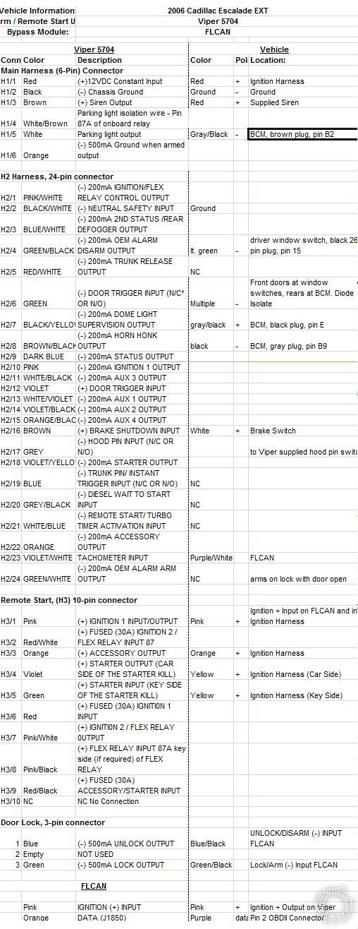
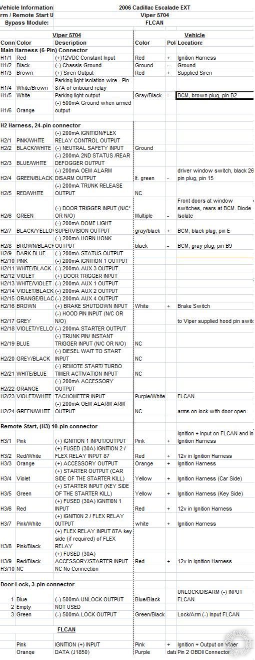
If you wanted to power the Brown ACC2 wire, here is the relay wiring :
Relay Pin 85 to Viper H2/22 Orange (-) 200mA Accessory Output
Relay Pin 86 and 87 to +12V Constant thru 20 Amp fuse
Relay Pin 30 to Escalade Brown ACC2 wire @ ignition harness
Relay Pin 87a not used - insulate
Soldering is fun!
Page of 2

  Printable version Printable version Post ReplyPost New Topic
You cannot post new topics in this forum
You cannot reply to topics in this forum
You cannot delete your posts in this forum
You cannot edit your posts in this forum
You cannot create polls in this forum
You cannot vote in polls in this forum

  •  
Search the12volt.com
Follow the12volt.com Follow the12volt.com on Facebook
Wednesday, April 24, 2024 • Copyright © 1999-2024 the12volt.com, All Rights Reserved Privacy Policy & Use of Cookies
Disclaimer: *All information on this site ( the12volt.com ) is provided "as is" without any warranty of any kind, either expressed or implied, including but not limited to fitness for a particular use. Any user assumes the entire risk as to the accuracy and use of this information. Please verify all wire colors and diagrams before applying any information.

Secured by Sectigo
the12volt.com spacer
Support the12volt.com
Top
the12volt.com spacer