the12volt.com spacer
icon

2005 nissan pathfinder viper 5704


Post ReplyPost New Topic
< Prev Topic Next Topic >
aharrison999 
Member - Posts: 6
Member spacespace
Joined: December 19, 2013
Location: Missouri, United States
Posted: December 23, 2013 at 8:25 PM / IP Logged  
Trying D2D with W2W as a backup plan sounds like a great idea to me.
It does have factory alarm, does that mean I have to hardwire to arm/disarm the factory alarm or will the d2d handle that?
I don't see a factory hood pin... Guess that means I need to install one... or can I just ground the hood pin wire?
kreg357 
Platinum - Posts: 7,781
Platinum spaceThis member has made a donation to the12volt.com. Click here for more info.spaceThis member has been recognized as an authority in Electrical Theory. Click here for more info.spaceThis member has been recognized as an authority in Mobile Security and Convenience. Click here for more info.spacespace
Joined: January 30, 2009
Location: Pennsylvania, United States
Posted: December 23, 2013 at 9:14 PM / IP Logged  

Factory Alarm is additional labor.   Check your BCM 40 Pin Plug for these wires

Lock/Arm   BCM White 40     pin 08 LtBlue (-) BCM right of steering column
Unlock/Disarm    BCM White 40     pin 07 Gray (-) BCM right of steering column
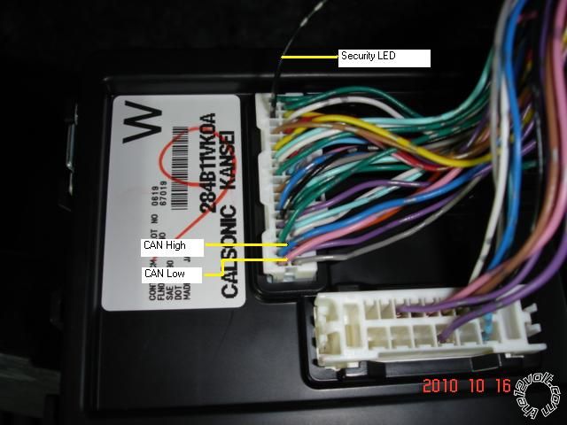
Here is a photo of a BCM ( 2011 Rogue )  :

2005 nissan pathfinder viper 5704 - Page 2 -- posted image.

If the wires are not there and the pins are empty you will need a few 1N400x diodes.  RadioShack usually has them.  You can get

1N4001, 1N4004 or 1N4007 diodes.  You will be inserting a diode leg into the BCM empty pin holes for Lock and Unlock.  The
diodes leg diameter is the correct size to make solid contact with the BCM connector inside.  Solder the R/S's Lock and Unlock
wire outputs to the diodes other leg, diode stripe towards the R/S.  Use heat shrink tube to insulate this wire / diode assy and
secure it to the other wires in the BCM's harness with tie wraps or electrical tape to prevent it from being pulled out.  The DLPK
install guide has a diagram of the BCM connector and the empty pin locations.

The photo above also shows the CAN wires.  You can get the CAN wires at the OBD2 connector, too.

CanHi      OBD2 White 16     pin 06 Blue (DATA)

CanLo     OBD2 White 16     pin 14 Pink (DATA)

Test for the Factory Hood Pin by sitting in the Pathfinder and setting it's alarm.  Wait a few minutes and pull the hood release.

If the horn starts beeping, the hood is monitored and the DLPK will provide a Hood Trigger signal.  If it does not set off the alarm,
you can add the hood pin supplied in the kit.  It is  used for both the Viper Alarm system and the Viper remote start system.
It will prevent a remote start if the hood is open ( like during engine service ) and will shutdown a remote started engine if the
hood is opened.  If you don't want to drill a hole in your Pathfinder, you can either fabricate a mounting bracket that uses
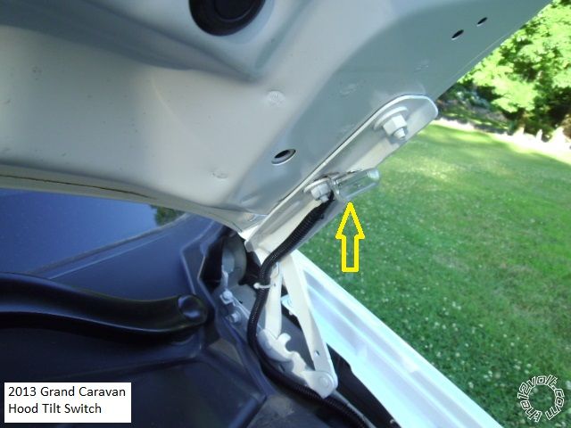
existing bolts or use a mercury tilt switch mounted as shown below :

2005 nissan pathfinder viper 5704 - Page 2 -- posted image.

Please note that a mercury tilt switch, when adjusted properly, will not trigger until the hood is raised at least half way open.

Soldering is fun!
magnamagus 
Member - Posts: 19
Member spacespace
Joined: January 23, 2014
Location: Arizona, United States
Posted: February 06, 2014 at 2:41 AM / IP Logged  
Question:
When making connections to the BCM Lock and unlock, you stated that the Diode Stripe side (-) should be pointed toward the remote start, and the Positive side is connected to the BCM.
1. Does this protect the BCM by preventing positive current going into the BCM?
2. Are the Lock and Unlock wires necessary if these are handled by the BYPASS MODULE?
Erick
bknudsen89 
Member - Posts: 12
Member spacespace
Joined: October 23, 2014
Location: Florida, United States
Posted: October 23, 2014 at 2:39 PM / IP Logged  
Kreg357:
I am also doing my first ever rs install of the viper 4104 w/ dball2. I was looking over this post and first of all thank you so much for all of your knowledge. I am a little confused though as to what I need to do with all of those 30A fuse lines that are connected to 12V constant ( those not being connected to a relay). For my car at the ignition switch it shows the 12V Constant wire as green. Do all of these connections divide into this one wire? Or how do you propose these are connected? Using diodes? Sorry if I'm a bit confusing all help would be appreciated.
howie ll 
Pot Metal - Posts: 16,466
Pot Metal spacespace
Joined: January 09, 2007
Location: United Kingdom
Posted: October 23, 2014 at 5:11 PM / IP Logged  
Last poster, make model and year please, never seen a green 12V+ constant.
For most manufacturers it's white, WHITE/ red, and red plus one or two e.g.Toyota, black
bknudsen89 
Member - Posts: 12
Member spacespace
Joined: October 23, 2014
Location: Florida, United States
Posted: October 23, 2014 at 5:41 PM / IP Logged  
2013 Nissan sentra Sr standard key.
howie ll 
Pot Metal - Posts: 16,466
Pot Metal spacespace
Joined: January 09, 2007
Location: United Kingdom
Posted: October 23, 2014 at 5:44 PM / IP Logged  
Find the wire that gives a constant 12V+ at the ignition, probably white or WHITE/ red join the red at H1 and the red, RED / white and RED / black there, alternative, thick white feeding the fuse box. Green? Bet that's something else, usually lighting on Japanese cars.
howie ll 
Pot Metal - Posts: 16,466
Pot Metal spacespace
Joined: January 09, 2007
Location: United Kingdom
Posted: October 23, 2014 at 5:46 PM / IP Logged  
Find the wire that gives a constant 12V+ at the ignition, probably white or WHITE/ red join the red at H1 and the red, RED / white and RED / black there, alternative, thick white feeding the fuse box.
Oops,just checked you're quite correct its green.
bknudsen89 
Member - Posts: 12
Member spacespace
Joined: October 23, 2014
Location: Florida, United States
Posted: October 23, 2014 at 5:56 PM / IP Logged  
No problem I even double checked because I'm no professional.
bknudsen89 
Member - Posts: 12
Member spacespace
Joined: October 23, 2014
Location: Florida, United States
Posted: October 23, 2014 at 6:42 PM / IP Logged  
Ok. So I have one constant,one starter, one ignition, and two accessory wires. I have the starter, accessory 1, ignition, and 12V constant wired directly into the corresponding viper wires. I then have accessory two wired to a SPDT 40A relay via the accessory(- 200mA) and the white accessory 2 wire out of the ignition switch harness then 12V constant power to the other two leads, much like was recommended for the starter 2 wire of the pathfinder. I'm just checking to see if I've done this correctly. Thanks
Page of 2

Sorry, you can NOT post a reply.
This topic is closed.

  Printable version Printable version Post ReplyPost New Topic
You cannot post new topics in this forum
You cannot reply to topics in this forum
You cannot delete your posts in this forum
You cannot edit your posts in this forum
You cannot create polls in this forum
You cannot vote in polls in this forum

  •  
Search the12volt.com
Follow the12volt.com Follow the12volt.com on Facebook
Thursday, March 28, 2024 • Copyright © 1999-2024 the12volt.com, All Rights Reserved Privacy Policy & Use of Cookies
Disclaimer: *All information on this site ( the12volt.com ) is provided "as is" without any warranty of any kind, either expressed or implied, including but not limited to fitness for a particular use. Any user assumes the entire risk as to the accuracy and use of this information. Please verify all wire colors and diagrams before applying any information.

Secured by Sectigo
the12volt.com spacer
Support the12volt.com
Top
the12volt.com spacer