the12volt.com spacer
icon

power distribution


Post ReplyPost New Topic
< Prev Topic Next Topic >
ronemca 
Copper - Posts: 107
Copper spacespace
Joined: November 09, 2012
Location: Ontario, Canada
Posted: December 24, 2013 at 2:52 PM / IP Logged  
I have already installed two relays under the hood, and/but I am getting set to install two more. I have tried my best to consolidate the assorted wires, but of course each relay has four leads, and since all four of them will be feeding/controlling a wireless switch -- (also under the hood) -- the wiring is already messy. And when I add the next pair of relays it's gonna be a canine's evening repast.
What I would therefore like is a small box -- preferably without fuses -- to which I can supply ONE power lead...and FROM WHICH I can supply five or six devices.
I know there are replacement battery terminals that allow this, and I also know there are multi-fused terminal blocks...AND non-fused terminal blocks. But I already have inline fuses for my two existing feeds (and yeah - I could re-config those, but I'd rather not) And of course the non-fused blocks require as many inputs as there are active outputs (so that kills the one-in-many-out premise)
I have found a red plastic block that has about eight screws around the base and a 5/16" screw sticking out the top (it looks like a crown; all of the connections are completely exposed). I guess it would do the job...but it's a bit ghetto for my taste.
My connections are about 14g or 16g (as opposed to 4g or 0g) so I don't want or need to replace the POS battery terminal. But aside from that, are there any other options? And/or some online sources that I could visit for ideas (and perhaps product)?
Many thanks, and Merry Christmas!
Ween 
Platinum - Posts: 1,364
Platinum spacespace
Joined: August 01, 2004
Location: Illinois, United States
Posted: December 24, 2013 at 6:41 PM / IP Logged  
hi,
you have a power feed input for six circuits.
total current required as well as for each branch?
this will be for the sizing of the input stud as well as wiring in the unit.
control signals are positive or negative? or both?
this is for the number of input/output terminals needed.
a die cast aluminum box to mount six relays inside, these boxes can be bought with mounting flanges. terminal strip along long edge for input/output connections.
power feed through on box as well for well power input.
mark
ronemca 
Copper - Posts: 107
Copper spacespace
Joined: November 09, 2012
Location: Ontario, Canada
Posted: December 24, 2013 at 11:53 PM / IP Logged  
Ween wrote:
hi, total current required as well as for each branch?
I haven't added it up. At this point I have the two relays mounted and the circuits are working perfectly. In theory I didn't need the relays, because the wireless control boxes are rated at 15A...which I believe is quite enough headroom for what I'm running.
On circuit #1 (R1) I have a single 7" HID light.
On circuit #2 (R2) I have a pair of 4" Halogen lights.
On circuit #3(R3) -- which does not yet exist -- it's going to be a 20" LED lightbar which contains 40 LED's (infinitesimal draw).
But I was a little apprehensive about the wireless control boxes. Clearly the "switch" circuitry is integrated onto a fairly small board inside the box, and I didn't want to take any chances of frying those skinny strips of copper and/or diodes or whatever is inside there. Hence the relays.
Ween wrote:
control signals are positive or negative?
Positive; the remote trigger for each relay is provided by the activation of the wireless remote keyfob inside the vehicle.
Ween wrote:
a die cast aluminum box to mount six relays inside, these boxes can be bought with mounting flanges. terminal strip along long edge for input/output connections.
Not entirely sure what you mean here. Are you suggesting a small aluminum box? Sortof 2" x 4" x 8"? And it has flanges inside? May I please see an example?
Ween wrote:
power feed through on box as well for well power input.
mark
Completely stumped here. (Sorry) I believe we are talking about an aluminum box, inside of which are...let's say...four relays (one for future expansion). One "main" power wire enters the box from the battery, and (inside the box) feeds a bus bar of sorts(?) And from the bus bar four separate leads branch out to each of the four relays. Meanwhile, I have to also bring three separate trigger wires into the box, and...
bring out[/] of the box:
three separate power wires (one to each of the three lighting systems), and one common ground.
This sounds like alotta work for questionable gain. But I want to be sure I am understanding; I realize I have made several assumptions, and maybe I am over-thinking it!
I would also be very pleased to see the terminal bar you're talking about.
Thank you VERY kindly for replying! This will not happen tomorrow or anything...but I am eager to begin the collecting of components (and learning the answers to some of my questions!)
Merry Christmas!
ronemca 
Copper - Posts: 107
Copper spacespace
Joined: November 09, 2012
Location: Ontario, Canada
Posted: December 24, 2013 at 11:56 PM / IP Logged  
Ween wrote:
hi, <snip> total current required as well as for each branch?
I haven't added it up. At this point I have the two relays mounted and the circuits are working perfectly. In theory I didn't need the relays, because the wireless control boxes are rated at 15A...which I believe is quite enough headroom for what I'm running.
On circuit #1 (R1) I have a single 7" HID light.
On circuit #2 (R2) I have a pair of 4" Halogen lights.
On circuit #3(R3) -- which does not yet exist -- it's going to be a 20" LED lightbar which contains 40 LED's (infinitesimal draw).
But I was a little apprehensive about the wireless control boxes. Clearly the "switch" circuitry is integrated onto a fairly small board inside the box, and I didn't want to take any chances of frying those skinny strips of copper and/or diodes or whatever is inside there. Hence the relays.
Ween wrote:
control signals are positive or negative?
Positive; the remote trigger for each relay is provided by the activation of the wireless remote keyfob inside the vehicle.
Ween wrote:
a die cast aluminum box to mount six relays inside, these boxes can be bought with mounting flanges. terminal strip along long edge for input/output connections.
Not entirely sure what you mean here. Are you suggesting a small aluminum box? Sortof 2" x 4" x 8"? And it has flanges inside? May I please see an example?
Ween wrote:
power feed through on box as well for well power input.
mark
Completely stumped here. (Sorry) I believe we are talking about an aluminum box, inside of which are...let's say...four relays (one for future expansion). One "main" power wire enters the box from the battery, and (inside the box) feeds a bus bar of sorts(?) And from the bus bar four separate leads branch out to each of the four relays. Meanwhile, I have to also bring three separate trigger wires into the box, and...
bring out of the box:
three separate power wires (one to each of the three lighting systems), and one common ground.
This sounds like alotta work for questionable gain. But I want to be sure I am understanding; I realize I have made several assumptions, and maybe I am over-thinking it!
I would also be very pleased to see the terminal bar you're talking about.
Thank you VERY kindly for replying! This will not happen tomorrow or anything...but I am eager to begin the collecting of components (and learning the answers to some of my questions!)
Merry Christmas!
ronemca 
Copper - Posts: 107
Copper spacespace
Joined: November 09, 2012
Location: Ontario, Canada
Posted: December 25, 2013 at 12:21 AM / IP Logged  
Okay. As usual, I have asked more questions than I needed to. (I misunderstood your use of the word "flanges".) I now realize you're referring to a box that has flanges that are provided for mounting the box...rather than for mounting what is inside the box.
Like this?
Where's a good source for these at a decent price? (assuming this is indeed what you were suggesting!)
ronemca 
Copper - Posts: 107
Copper spacespace
Joined: November 09, 2012
Location: Ontario, Canada
Posted: December 25, 2013 at 11:28 AM / IP Logged  
I've sketched out what I think I need.
power distribution -- posted image.
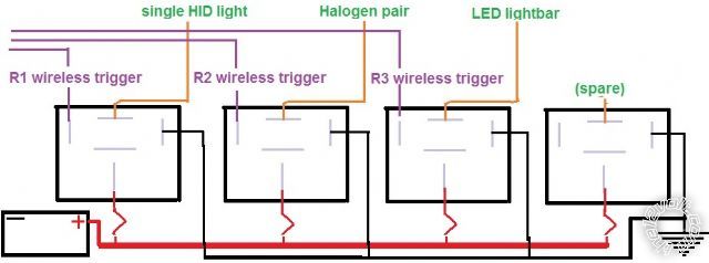
In the grand scheme of things, I believe this is what I should have done in the first place...rather than mounting and wiring each relay separately.
And I am also now thinking that it makes more sense to use a 5- or 6- terminal FUSE HOLDER/terminal block in the box, because it will:
a) reduce complexity
b) reduce wiring outside the box
c) be easier to find than a one-becomes-many terminal block...which would still require separate fuses anyway
However...
Aside from soldering (or the dreaded vampire clips - which I heartily dislike) I'm still not sure how to split ONE 8g or 10g power feeder into FOUR separate/smaller branches inside the box. I will have another look at the 5- or 6- fuse terminal blocks; perhaps one of those offers a one-in-many-out option.
ronemca 
Copper - Posts: 107
Copper spacespace
Joined: November 09, 2012
Location: Ontario, Canada
Posted: December 25, 2013 at 11:58 AM / IP Logged  
Holy cow - this is getting exciting! I've found almost exactly what I'm looking for:
power distribution -- posted image.
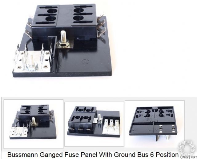
Ideally I only want FOUR terminals (which is already one more than I expect to need) but I can't find any one-in-many-out with fewer than six terminals.
Anyway - I like the first flat black one the best, because it also offers a ground bus...which is going to further simplify and condense my wiring.
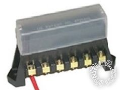
My next choice would be the second flat black one. Both look like an easier fit inside a die-cast box.
And my third choice would be...well...the third one.
Is there any advantage (or disadvantage) to any one of these options? Any features or possible problems that are not obvious from the photos? I've never worked with anything like this...but it certainly looks appealing!!
A big thanks to 'Ween' for steering me in this direction!!
Ween 
Platinum - Posts: 1,364
Platinum spacespace
Joined: August 01, 2004
Location: Illinois, United States
Posted: December 25, 2013 at 12:15 PM / IP Logged  
Ok,
    For the power input, something such as http://www.onlinecomponents.com/ bussmann-cooper-c29091.html? p=10804917. Or build one with shoulder washers (nylon washer with a step machined on one edge/end).
Slip a bolt through, secure with flat washers and nut.
    A ring terminal with multiple wires attached can distribute the power to individual relays. A single wire could distribute to an internal fuse block, output of the fuse block to the relays.
    Sockets and terminals, pigtailed relay sockets or individual terminals for connections to your relays.
    Input and output connections are one by a feed through barrier terminal strip. Individual terminals should be good for 15A each.
    If the receiver is to be mounted underhood, the box (being aluminum) would probably shield reception if the receiver is mounted internally. A plastic case of similar style would be one option.
Mark
Ween 
Platinum - Posts: 1,364
Platinum spacespace
Joined: August 01, 2004
Location: Illinois, United States
Posted: December 25, 2013 at 12:34 PM / IP Logged  
Here is an idea for the barrier strip; http://www.molex.com/ pdm_docs/sd/387203212_sd.pdf
And a shoulder washer...a bit overkill for the application; http://www./itm/ WORKMAN-CB-RADIO-ANTENNA-SO -239-STUD-MOUNT-REPLACEMEN T-NYLON-WASHERS- BULK-/121176591696? pt=US_Radio_Comm_Device _Mounts&hash=item1c36b00d50
Application showing washer in use; http://www./itm/Workman- SM2-Brass-3-8-x-24-Lug -Terminal-Type-Stud-Mount- CB-RADIO-Antenna- /370954745110? pt=US_Radio_Comm_Device_Mounts &hash=item565ea03516
The case would be in the stepped down portion between the metal ends.
ronemca 
Copper - Posts: 107
Copper spacespace
Joined: November 09, 2012
Location: Ontario, Canada
Posted: December 25, 2013 at 9:43 PM / IP Logged  
This is the part in the adventure where -- when I say:
"Hmm - I think I'm going to..."
I look like an ignorant ass*** because I am not taking suggestions. power distribution -- posted image. But that is not the case, gentlemen. I don't see myself mounting a post thru any sort of box. Not only because it introduces additional/superfluous/unnecessary connections, but also because it creates at least one more place for corrosion that needn't be present, because...
I have a two-piece silicone-lined firewall pass-through which will permit me to run my 8g feeder straight from the battery to the distribution block in one uninterrupted length.
If I can't ground the box by its mounting screws (and ground my relays to the inside of the box) I should be able to bring a GRND wire out the same pass-through to chassis GRND.
Admittedly the end result will not be completely waterproof (as it likely would be with your suggestions) but it'll be damn close. And a lot better than what I have NOW.
Besides - this is not a creek-swimming Humvee we're talking about here; if I am submerged deeply enough that my relay box is in danger of being swamped I'll have bigger things to occupy my mind than a few wires under the hood!
All this aside, I wouldn't have been looking in this direction without your smart & patient suggestions. So - thank you! I am most grateful.
BTW - do any of you have an opinion and/or first-hand experiences to share re: the three blocks I pictured above?
Page of 13

  Printable version Printable version Post ReplyPost New Topic
You cannot post new topics in this forum
You cannot reply to topics in this forum
You cannot delete your posts in this forum
You cannot edit your posts in this forum
You cannot create polls in this forum
You cannot vote in polls in this forum

  •  
Search the12volt.com
Follow the12volt.com Follow the12volt.com on Facebook
Thursday, April 18, 2024 • Copyright © 1999-2024 the12volt.com, All Rights Reserved Privacy Policy & Use of Cookies
Disclaimer: *All information on this site ( the12volt.com ) is provided "as is" without any warranty of any kind, either expressed or implied, including but not limited to fitness for a particular use. Any user assumes the entire risk as to the accuracy and use of this information. Please verify all wire colors and diagrams before applying any information.

Secured by Sectigo
the12volt.com spacer
Support the12volt.com
Top
the12volt.com spacer