


power distribution


Posted: December 25, 2013 at 10:00 PM / IP Logged


Posted: December 25, 2013 at 10:53 PM / IP Logged
Posted: December 26, 2013 at 6:11 AM / IP Logged
Posted: December 26, 2013 at 7:31 AM / IP Logged
Posted: December 26, 2013 at 5:56 PM / IP Logged
Posted: December 26, 2013 at 11:06 PM / IP Logged
Posted: December 27, 2013 at 7:43 PM / IP Logged
Posted: December 27, 2013 at 7:57 PM / IP Logged
Posted: December 27, 2013 at 8:17 PM / IP Logged
Posted: December 28, 2013 at 4:37 PM / IP Logged
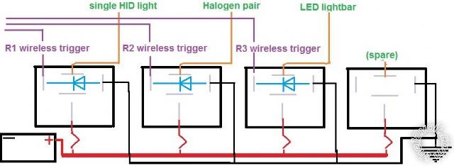 I have begun the wiring by inserting the diodes into the circuit in parallel across the coil terminals as shown. The actual science is a bit fuzzy, but I'm trying to grasp it.
As I see it, the diodes do not (cannot) block any electricity when the coil is energized because:
a) the electricity is flowing through the coil from + to - and effectively "bypassing" the diode
b) there is not (or should not) be any energy flowing "backwards" from the NEG side of the relay anyway
But -- at the instant the coil is DE-energized -- there is residual energy in the coil that could theoretically cause problems. And the sudden discharge/collapse/burst of this residual energy is blocked/dissipated by the diode so that it cannot travel...to...where, exactly?
When the coil is DE-energized, the residual energy in the coil is expected to "loop" "back" through the diode...and thence deplete itself by running in a closed loop until dissipated. And this is intended to "shield" the upstream components (in my case, a wireless switch) from that trace of reversing energy.
However...
The trigger wire remains attached to the POS side of the relay all the time. And if the diode is wired in parallel across the coil terminals...it too is therefore attached to the trigger wire all the time.
So...
Assuming that the flow of electricity "exits" the coil at the NEG side when the coil is energized, when the coil is DE-energized, does the residual energy in the coil continue to flow in that same direction? If yes, then most of it will go to GROUND, and any tiny bit that tries to sneak back through the diode will be blocked...and therefore NOT reach the wireless switch. :)
But is it possible for it to "leak" backwards? (reverse direction?) If so, then it will encounter the K end of the diode, which will allow it to pass through the diode and re-enter at the NEG end. Which is okay. But it will also encounter the trigger wire. So what's stopping it from travelling upstream back to the wireless switch?
I have begun the wiring by inserting the diodes into the circuit in parallel across the coil terminals as shown. The actual science is a bit fuzzy, but I'm trying to grasp it.
As I see it, the diodes do not (cannot) block any electricity when the coil is energized because:
a) the electricity is flowing through the coil from + to - and effectively "bypassing" the diode
b) there is not (or should not) be any energy flowing "backwards" from the NEG side of the relay anyway
But -- at the instant the coil is DE-energized -- there is residual energy in the coil that could theoretically cause problems. And the sudden discharge/collapse/burst of this residual energy is blocked/dissipated by the diode so that it cannot travel...to...where, exactly?
When the coil is DE-energized, the residual energy in the coil is expected to "loop" "back" through the diode...and thence deplete itself by running in a closed loop until dissipated. And this is intended to "shield" the upstream components (in my case, a wireless switch) from that trace of reversing energy.
However...
The trigger wire remains attached to the POS side of the relay all the time. And if the diode is wired in parallel across the coil terminals...it too is therefore attached to the trigger wire all the time.
So...
Assuming that the flow of electricity "exits" the coil at the NEG side when the coil is energized, when the coil is DE-energized, does the residual energy in the coil continue to flow in that same direction? If yes, then most of it will go to GROUND, and any tiny bit that tries to sneak back through the diode will be blocked...and therefore NOT reach the wireless switch. :)
But is it possible for it to "leak" backwards? (reverse direction?) If so, then it will encounter the K end of the diode, which will allow it to pass through the diode and re-enter at the NEG end. Which is okay. But it will also encounter the trigger wire. So what's stopping it from travelling upstream back to the wireless switch? Printable version
| You cannot post new topics in this forum You cannot reply to topics in this forum You cannot delete your posts in this forum You cannot edit your posts in this forum You cannot create polls in this forum You cannot vote in polls in this forum |

| Search the12volt.com |
Follow the12volt.com 
Tuesday, May 12, 2026 • Copyright © 1999-2026 the12volt.com, All Rights Reserved • Privacy Policy & Use of Cookies

Tuesday, May 12, 2026 • Copyright © 1999-2026 the12volt.com, All Rights Reserved • Privacy Policy & Use of Cookies
Disclaimer:
*All information on this site ( the12volt.com ) is provided "as is" without any warranty of any kind, either expressed or implied, including but not limited to fitness for a particular use. Any user assumes the entire risk as to the accuracy and use of this information. Please
verify all wire colors and diagrams before applying any information.
