the12volt.com spacer
icon

1999-2002 Silverado Remote Start w/Keyless Pictorial


Post ReplyPost New Topic
< Prev Topic Next Topic >
kreg357 
Platinum - Posts: 7,795
Platinum spaceThis member has made a donation to the12volt.com. Click here for more info.spaceThis member has been recognized as an authority in Electrical Theory. Click here for more info.spaceThis member has been recognized as an authority in Mobile Security and Convenience. Click here for more info.spacespace
Joined: January 30, 2009
Location: Pennsylvania, United States
Posted: January 11, 2014 at 4:12 PM / IP Logged Link to Post Post Reply Quote kreg357

This is a DIY Pictorial on installing a remote start with keyless entry system into a 1999 through 2002 Silverado.   This pictorial specifically covers trucks with automatic transmissions and gasoline engines.   The GMC full size Pickup ( Sierra ) will be the same for these years, too.

These trucks have the Passlock2 engine immobilizer system.  There are many bypass modules available.  Depending on your skill level and budget, you can use anything from "relays and resistor method " to the newer "data" style bypass modules.  For this install, an iDatalink ADS TBSL PL bypass module was chosen.   Due to the ease of access to the necessary wires, a "full function" bypass module was deemed un-necessary for this install.

Any quality remote start system can be used.  This truck needs (+) Parking Light and (+) Door Lock outputs from the R/S system. While all R/S systems can provide (+) Parking Light output, most newer R/S systems only provide (-) door lock outputs, so either relays or a Directed 451M module is needed to make the (-) to (+) conversion.

For this install, an Avital 4103 remote start system and a Directed 451M door lock module was used.  Below are the wire connections :

H1/1  LIGHT GREEN/ BLACK  FACTORY ALARM DISARM               Lt. Green (driver door key cylinder) (-)  BCM, purple plug, pin B3

H1/2  GREEN / WHITE  FACTORY REARM                                         not used
H1/3  YELLOW  (+) IGNITION OUT (TO ALARM)                               not used
H1/4  WHITE/ BLUE  (-) ACTIVATION INPUT                                      not used
H1/5  ORANGE  (-) GROUND WHEN LOCKED                                  not used
H1/6  BROWN  (-) HORN OUTPUT                                                     Black (-)  BCM, brown plug, pin A9
H1/7  RED / WHITE  (-) TRUNK RELEASE OUTPUT                           not used
H1/8  BLACK  GROUND                                                                      Chassis Ground ( also has ADS TBSL PL Black wire )
H1/9  WHITE  (+/-) LIGHT FLASH    *** Set to (+) ***                          Brown (+)  BCM, lt. blue plug, pin B6

H2/1  BLACK/ WHITE  (-) NEUTRAL SAFETY SWITCH INPUT            Chassis Ground ( auto trans only! )

H2/2  VIOLET/WHITE  TACHOMETER INPUT WIRE                           White (ac)  instrument cluster
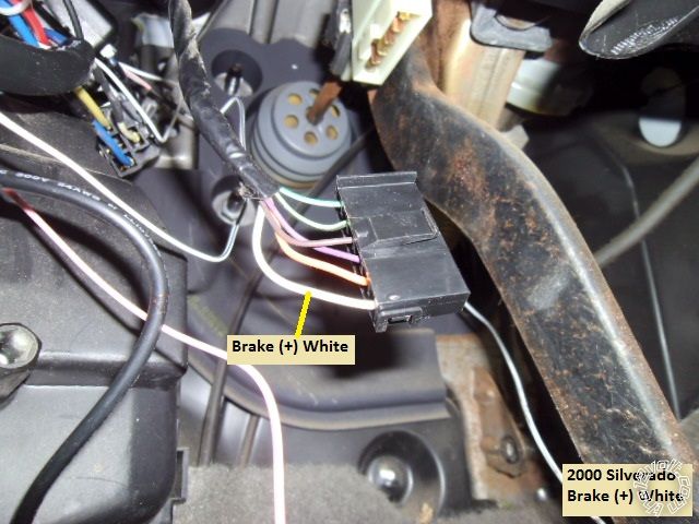
H2/3  BROWN  (+) BRAKE SWITCH SHUTDOWN WIRE                     White (+)  brake switch
H2/4  GRAY  (-) HOOD PINSWITCH SHUTDOWN WIRE                     to Avital kit supplied hood pin
H2/5  BLUE/WHITE  (-) 200mA 2ND STATUS/DEFOG OUTPUT         not used

4-pin satellite harness diagram

1  BLUE  STATUS OUTPUT                                                                   to ADS TBSL PL Blue/White @ 4 pin connector
2  ORANGE  (-) ACCESSORY OUTPUT                                                to extra Relay Pin 85
3  PURPLE  (-) STARTER OUTPUT                                                       not used
4  PINK  (-) IGNITION OUTPUT                                                              not used

Heavy gauge relay wiring diagram

1  PINK  (+) (30 AMP) OUTPUT TO IGNITION CIRCUIT                       Pink (+)  ignition harness ( also has ADS TBSL PL Pink wire )
2  PURPLE  (+) (30 AMP) OUTPUT TO STARTER CIRCUIT                Yellow (+)  ignition harness
3  ORANGE  (+) (30 AMP) OUTPUT TO ACCESSORY CIRCUIT         Orange (+)  ignition harness
4  RED  (+) (30A) HIGH CURRENT 12 INPUT                                       Red  (+)  ignition harness ( also has 451M Violet/Black wire )
5  PINK/WHITE  (+) PROGRAMMED FOR IGNITION2                          White (+)  ignition harness
6  RED  (+) (30A) HIGH CURRENT 12V INPUT                                     RED / White  (+)  ignition harness ( also has ADS TBSL PL Red wire )

Door lock harness, 3-pin connector

1  BLUE  (-) UNLOCK OUTPUT                                                                plug in Directed 451M connector
2  EMPTY  NOT USED                                                                              plug in Directed 451M connector
3  GREEN  (-) LOCK OUTPUT                                                                  plug in Directed 451M connector

Extra 30/40 Amp SPDT relay for Brown ACC2 wire :

Relay Pin 85 to Avital  ORANGE  (-) ACCESSORY OUTPUT 
Relay Pin 86 and 87 to Silverado RED / White  (+)  ignition harness through 30 Amp fuse
Relay Pin 30 to Silverado Brown ACC2 wire @ ignition harness
Relay Pin 87a not used

ADS TBSL PL

4 Pin plug
Red to Avital heavy gauge RED / White wire
Black to Avital H1/8 Black wire
Blue/White to Avital BLUE  (-) STATUS OUTPUT

9 Pin plug

Pink to Avital heavy Pink IGN1 wire
Orange to Silverado Violet wire @ OBD2 Pin 2

Directed 451M

3 Pin plug        to Avital Door Lock connector
Violet/Black w/15 Amp fuse             to Avital Red wire ( which goes to Silverado Red @ ignition harness )
WHITE/ Black     not used
BROWN / Black    not used
GREEN/ Black    to Silverado Lt. Blue (+)  BCM, brown plug, pin A4
Blue/Black       to Silverado White (+)  BCM, brown plug, pin A3

A few notes :  This truck had the Factory Alarm and power door locks, some don't.   The wiring above reflects that.  I chose to power the Brown ACC2 wire during remote start and therefore needed an additional high power output.  The extra relay handled this additional ignition circuit.  The ADS TBSL PL handled the Passlock2 bypass via its' lone connection to the Violet wire at Pin 2 of the OBD2 connector.  Very easy, very reliable but more expensive than other methods.  Because of this, I did not get a photo of the Passlock2 wires that are typically used with other bypass modules.

Disassembly :

Set the tilt steering wheel to its' lowest position.  Turn the ignition key to ON, press the brake pedal and move the gear selector to the bottom position.  Remove the instrument cluster bezel by pulling it straight away from the dash.  Remove the four 7mm screws that retain the instrument cluster and gently pull the cluster out.  There is no need to disconnect the cluster harness, as there is plenty of slack in the harness.  Lay the cluster on the dash.  Move the shifter back to Park and remove the ignition key.  Raise the tilt steering to it's highest position.  Remove the two screws at the bottom corners of the lower dash panel, then

pull it straight away from the dash.

Remove the four 10mm nuts shown using a deep socket and then remove the metal plate.
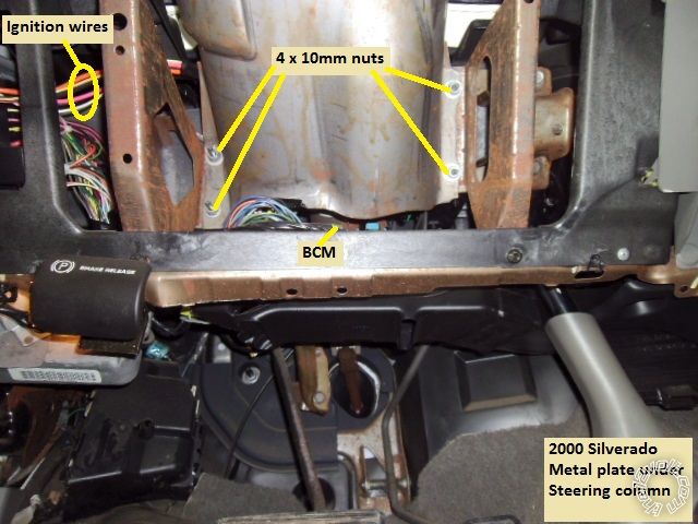
1999-2002 Silverado Remote Start w/Keyless Pictorial -- posted image.

At this point the BCM and ignition wires are accessible.  No need to remove the steering column covers.

Wires:

This is a picture of the main ignition wires as they leave the left side of the steering column and pass above the BCM.
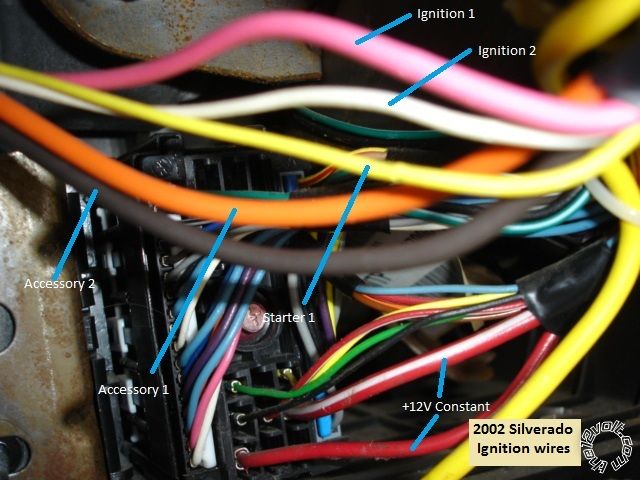
1999-2002 Silverado Remote Start w/Keyless Pictorial -- posted image.

This is a close-up photo of the +12V constant wires :
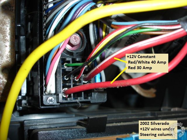
1999-2002 Silverado Remote Start w/Keyless Pictorial -- posted image.

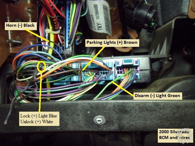
This is a shot of the BCM with the necessary wire marked :
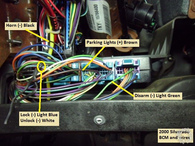
1999-2002 Silverado Remote Start w/Keyless Pictorial -- posted image.

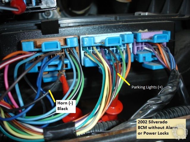
This is a close-up of the Horn wire at the BCM :
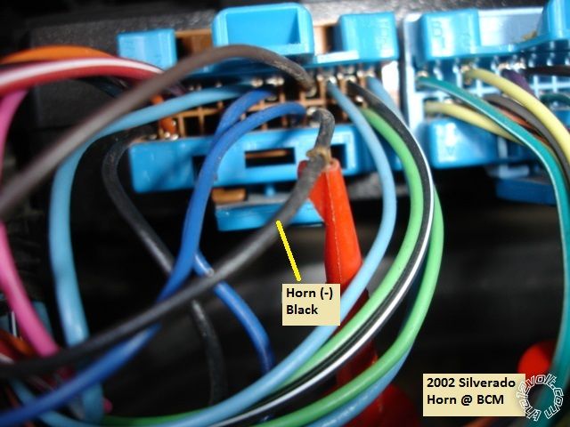
1999-2002 Silverado Remote Start w/Keyless Pictorial -- posted image.

This is a close-up of the Parking Light wire ( and Horn ) at the BCM :
1999-2002 Silverado Remote Start w/Keyless Pictorial -- posted image.

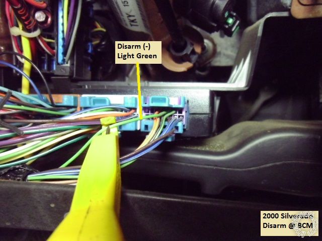
If your truck has the Factory Alarm, here is a photo of the Disarm wire :
1999-2002 Silverado Remote Start w/Keyless Pictorial -- posted image.

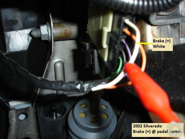
These are pictures of the Bake wire :
1999-2002 Silverado Remote Start w/Keyless Pictorial -- posted image.

1999-2002 Silverado Remote Start w/Keyless Pictorial -- posted image.

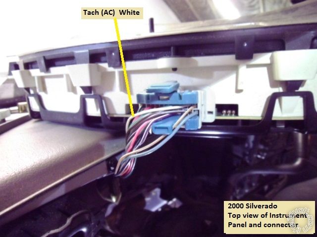
This is a photo of the Tach wire ( instrument cluster removed and resting on dash ) :
1999-2002 Silverado Remote Start w/Keyless Pictorial -- posted image.

Here is a picture of another Tach source, any Fuel Injector :
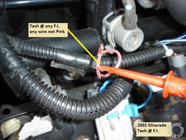
1999-2002 Silverado Remote Start w/Keyless Pictorial -- posted image.

Here is a picture of the OBD2 connector and the Violet Data wire at Pin 2 :
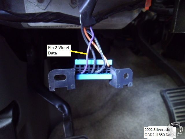
1999-2002 Silverado Remote Start w/Keyless Pictorial -- posted image.

Firewall pass-through is available at the main wiring harness grommet and exits behind the vacuum brake reservoir. 

While this Pictorial shows the necessary wires, you should still locate and verify these connection points with a Digital Multi Meter before soldering on the R/S's wires. 

The parts used for this install ( Avital 4103 = $50, ADS TBSL PL= $40, 30/40 Amp SPDT Relay w/harness = $4, inline ATC fuseholder with 30 Amp fuse = $3 & DEI 451M = $9 ) cost around $106.  This is probably less that getting a replacement factory keyless entry FOB with programming from the dealer.

Soldering is fun!
pts760 
Copper - Posts: 403
Copper spacespace
Joined: December 11, 2009
Location: United States
Posted: February 16, 2014 at 11:33 AM / IP Logged Link to Post Post Reply Quote pts760
Aren't those lock/unlock wires at the brown plug on the BCM (+) trigger not (-) trigger.
I drink current, eat ohms, and bleed voltage
kreg357 
Platinum - Posts: 7,795
Platinum spaceThis member has made a donation to the12volt.com. Click here for more info.spaceThis member has been recognized as an authority in Electrical Theory. Click here for more info.spaceThis member has been recognized as an authority in Mobile Security and Convenience. Click here for more info.spacespace
Joined: January 30, 2009
Location: Pennsylvania, United States
Posted: February 16, 2014 at 3:23 PM / IP Logged Link to Post Post Reply Quote kreg357

Good catch, PTS760!  I completely missed that error.  The Lock wires in these trucks are definitely (+).  ( Need to hire a proof reader...)

Here is an updated photo with the corrected wire polarities :

1999-2002 Silverado Remote Start w/Keyless Pictorial -- posted image.

Additionally, there is a mixture of photo's in the Pictorial.  Some from a 2002 without power locks and some from a 2000 with power locks and alarm.

Soldering is fun!
shesachevy99 
Member - Posts: 8
Member spacespace
Joined: April 10, 2014
Location: Alberta, Canada
Posted: April 16, 2014 at 10:52 PM / IP Logged Link to Post Post Reply Quote shesachevy99
I'm currently installing a viper remote start on my silverado and I'm getting a 12v reading on my factory disarm. Why am I getting this reading?
The thing about them Chevy's is they always get you home. Just kick the fuel pump a few times
auto enhancers 
Copper - Posts: 203
Copper spacespace
Joined: April 09, 2012
Location: Indiana, United States
Posted: April 17, 2014 at 8:52 AM / IP Logged Link to Post Post Reply Quote auto enhancers
because it rests at 12 volts, it is triggered by ground.
kreg357 
Platinum - Posts: 7,795
Platinum spaceThis member has made a donation to the12volt.com. Click here for more info.spaceThis member has been recognized as an authority in Electrical Theory. Click here for more info.spaceThis member has been recognized as an authority in Mobile Security and Convenience. Click here for more info.spacespace
Joined: January 30, 2009
Location: Pennsylvania, United States
Posted: April 17, 2014 at 10:00 AM / IP Logged Link to Post Post Reply Quote kreg357

As auto enhancers said.  1999-2002 Silverado Remote Start w/Keyless Pictorial -- posted image.   You are looking for a (-) pulse signal.  The wire at rest could be +12V or a float

The correct DMM setup for locating a (-) type signal in a vehicle is :  DMM set to 20V DC, Red test lead to +12V constant, Black test lead to the suspect wire.   The DMM will briefly read +12V when the (-) signal is present.  The Horn and Disarm wires shown above are (-) type signals and can found using the above setup.  You could do this test with the Horn wire first ( you can reach the horn button and hold it to see the DMM results ) to get a feel for it.  Auto-ranging DMM's will react slower and very brief (-) pulse signals will be difficult to catch.

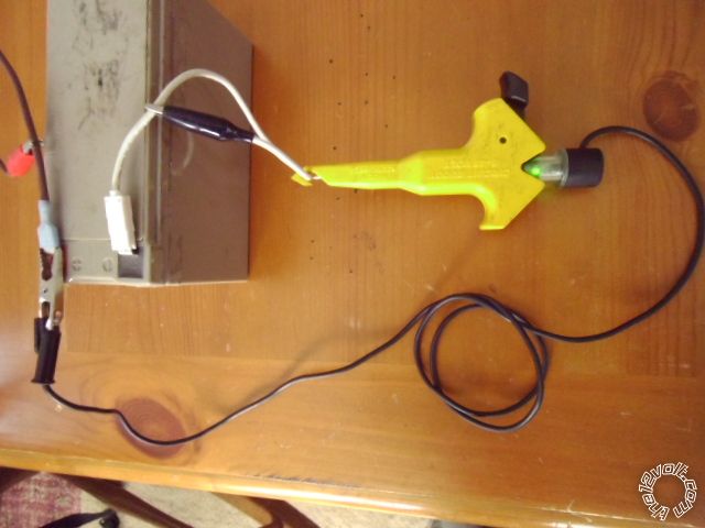
For wires like these in older vehicles, I use a "Computer Safe" LED test light like the one pictured below :

1999-2002 Silverado Remote Start w/Keyless Pictorial -- posted image.

It draws only 3mA and will give a Green LED indication when the signal is present.  It reacts quicker than a DMM and the Green LED is bright and easy to see.  The (-) Disarm photo shows the LED tester attached to the wire but does not include the upper section of the tester with the LED.

Soldering is fun!
shesachevy99 
Member - Posts: 8
Member spacespace
Joined: April 10, 2014
Location: Alberta, Canada
Posted: April 17, 2014 at 11:38 AM / IP Logged Link to Post Post Reply Quote shesachevy99
Thank you! I realized that after a good sleep.
The thing about them Chevy's is they always get you home. Just kick the fuel pump a few times
boricua bob 
Member - Posts: 24
Member spacespace
Joined: April 14, 2014
Location: Texas, United States
Posted: April 26, 2014 at 2:56 PM / IP Logged Link to Post Post Reply Quote boricua bob
where is the door trigger located, and the wait to start(im doing a 2001 3500 LS) and can i still use the same tach for the disel like ur picture says or do i have to use a diffrent tach?
kreg357 
Platinum - Posts: 7,795
Platinum spaceThis member has made a donation to the12volt.com. Click here for more info.spaceThis member has been recognized as an authority in Electrical Theory. Click here for more info.spaceThis member has been recognized as an authority in Mobile Security and Convenience. Click here for more info.spacespace
Joined: January 30, 2009
Location: Pennsylvania, United States
Posted: April 26, 2014 at 3:23 PM / IP Logged Link to Post Post Reply Quote kreg357

The White Tach wire at the back of the instrument cluster will work for the Diesel Engine.

Info from AudioVox for the Door Trigger :

    All Door Trigger  TAN/LIGHT BLUE  (-)    @ KEYLESS MODULE BELOW STEERING COLUMN Info from ReadyRemote for the door trigger :
    Door Trigger      Tan (-)      @ BCM, purple plug, pin B4  ( This is only the Drivers Door. ) Info from Bulldog Security :
   TAN (-) for the Drivers door located in PURPLE PLUG, PIN B4
   PASSENGER door use a ORANGE (-) in the PURPLE PLUG, PIN B2 or a DK BLUE/WHITE (-) in a LT BLUE PLUG, PIN B11
   when connecting an alarm you must use both wires and diode isolate.

Wait to start  Dark Blue (need to diode isolate see Tech Doc 1090)  - @ instrument cluster harness. Here is a link to a ZIP file that includes TechTip 1090 :  https://www.the12volt.com/installbay/file.asp?ID=1076 If your R/S system is capable you could use a Fixed Time Diesel Delay.

Soldering is fun!
boricua bob 
Member - Posts: 24
Member spacespace
Joined: April 14, 2014
Location: Texas, United States
Posted: April 26, 2014 at 3:48 PM / IP Logged Link to Post Post Reply Quote boricua bob
i'm installing a viper 5706v so i don't need the wait to start? what happens if i don't diode isolate the door trigger. i didn't do it on the 01 civic and everything works. i just connected the three wires together...
Page of 15

  Printable version Printable version Post ReplyPost New Topic
You cannot post new topics in this forum
You cannot reply to topics in this forum
You cannot delete your posts in this forum
You cannot edit your posts in this forum
You cannot create polls in this forum
You cannot vote in polls in this forum

  •  
Search the12volt.com
Follow the12volt.com Follow the12volt.com on Facebook
Tuesday, September 10, 2024 • Copyright © 1999-2024 the12volt.com, All Rights Reserved Privacy Policy & Use of Cookies
Disclaimer: *All information on this site ( the12volt.com ) is provided "as is" without any warranty of any kind, either expressed or implied, including but not limited to fitness for a particular use. Any user assumes the entire risk as to the accuracy and use of this information. Please verify all wire colors and diagrams before applying any information.

Secured by Sectigo
the12volt.com spacer
Support the12volt.com
Top
the12volt.com spacer