the12volt.com spacer
icon

xpressstart one, 2014 tundra


Post ReplyPost New Topic
< Prev Topic Next Topic >
dustintinsley 
Member - Posts: 17
Member spacespace
Joined: November 24, 2012
Location: Connecticut, United States
Posted: February 12, 2014 at 2:34 PM / IP Logged  
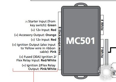
I finally got the XpressStart One installed on my 2014 Toyota Tundra. Got everything installed and remotes paired. When I hit the unlock button, it does indeed unlock. Same for the lock, it works as it should. When I hit the start button, it acts as if I have turned the key to the ON position but it does not start. The gauges come one and it cycles a few times but never cranks. I am guessing I have something wrong with my wiring at the ignition. Here is the diagrams I used:
xpressstart one, 2014 tundra - Page 2 - Last Post -- posted image.
My current setup at the ignition is as follows:
Green wire hooked up to Starter 1 (green wire # 7) at ignition switch
Red wire hooked up to +12v constant
Orange wire (accessory output) is not hooked up to anything
Red wire hooked up to +12v constant
Pink wire hooked up to Ignition 1 (black wire # 6) at ignition switch
RED / White wire hooked up to Ignition 2 (Lt. Green wire #1) at ignition switch
Pink/White wire not hooked up
I am sure those are incorrect. Can anyone please give me guidance on correct connections
kreg357 
Platinum - Posts: 7,783
Platinum spaceThis member has made a donation to the12volt.com. Click here for more info.spaceThis member has been recognized as an authority in Electrical Theory. Click here for more info.spaceThis member has been recognized as an authority in Mobile Security and Convenience. Click here for more info.spacespace
Joined: January 30, 2009
Location: Pennsylvania, United States
Posted: February 12, 2014 at 6:37 PM / IP Logged  
A couple corrections :
Green wire      hooked up to Starter 1 (green wire # 7) at ignition switch
Red wire          hooked up to +12v constant
Orange wire (accessory output)            hooked up to Gray wire @ Pin 2
Red wire          hooked up to +12v constant
Pink wire         hooked up to Ignition 1 (black wire # 6) at ignition switch
RED / White wire hooked up to +12V constant
Pink/White wire            hooked up to (Lt. Green wire #1) at ignition switch   *** Set for IGN2
Soldering is fun!
dustintinsley 
Member - Posts: 17
Member spacespace
Joined: November 24, 2012
Location: Connecticut, United States
Posted: February 12, 2014 at 7:37 PM / IP Logged  
how do i set pink/white wire fir IGN2?
kreg357 
Platinum - Posts: 7,783
Platinum spaceThis member has made a donation to the12volt.com. Click here for more info.spaceThis member has been recognized as an authority in Electrical Theory. Click here for more info.spaceThis member has been recognized as an authority in Mobile Security and Convenience. Click here for more info.spacespace
Joined: January 30, 2009
Location: Pennsylvania, United States
Posted: February 12, 2014 at 8:51 PM / IP Logged  
Not sure.  I don't have an install guide for that system.  It says Flex relay so it should be programmable.  The default is usually IGN2.
Soldering is fun!
dustintinsley 
Member - Posts: 17
Member spacespace
Joined: November 24, 2012
Location: Connecticut, United States
Posted: February 12, 2014 at 10:02 PM / IP Logged  
thanks for all the help. the above corrections worked. all is working now
Page of 2

Sorry, you can NOT post a reply.
This topic is closed.

  Printable version Printable version Post ReplyPost New Topic
You cannot post new topics in this forum
You cannot reply to topics in this forum
You cannot delete your posts in this forum
You cannot edit your posts in this forum
You cannot create polls in this forum
You cannot vote in polls in this forum

  •  
Search the12volt.com
Follow the12volt.com Follow the12volt.com on Facebook
Saturday, May 4, 2024 • Copyright © 1999-2024 the12volt.com, All Rights Reserved Privacy Policy & Use of Cookies
Disclaimer: *All information on this site ( the12volt.com ) is provided "as is" without any warranty of any kind, either expressed or implied, including but not limited to fitness for a particular use. Any user assumes the entire risk as to the accuracy and use of this information. Please verify all wire colors and diagrams before applying any information.

Secured by Sectigo
the12volt.com spacer
Support the12volt.com
Top
the12volt.com spacer