


xpressstart one, 2014 tundra
Home /
the12volt's Install Bay /
Car Security and Convenience / xpressstart one, 2014 tundra ( Topic Closed)


Posted: February 12, 2014 at 2:34 PM / IP Logged
 My current setup at the ignition is as follows:
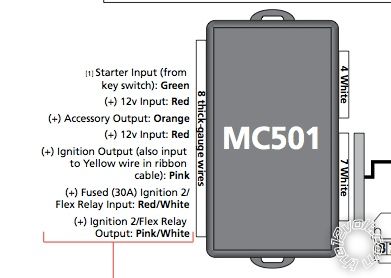
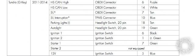
Green wire hooked up to Starter 1 (green wire # 7) at ignition switch
Red wire hooked up to +12v constant
Orange wire (accessory output) is not hooked up to anything
Red wire hooked up to +12v constant
Pink wire hooked up to Ignition 1 (black wire # 6) at ignition switch
RED / White wire hooked up to Ignition 2 (Lt. Green wire #1) at ignition switch
Pink/White wire not hooked up
I am sure those are incorrect. Can anyone please give me guidance on correct connections
My current setup at the ignition is as follows:
Green wire hooked up to Starter 1 (green wire # 7) at ignition switch
Red wire hooked up to +12v constant
Orange wire (accessory output) is not hooked up to anything
Red wire hooked up to +12v constant
Pink wire hooked up to Ignition 1 (black wire # 6) at ignition switch
RED / White wire hooked up to Ignition 2 (Lt. Green wire #1) at ignition switch
Pink/White wire not hooked up
I am sure those are incorrect. Can anyone please give me guidance on correct connections


Posted: February 12, 2014 at 6:37 PM / IP Logged
Posted: February 12, 2014 at 7:37 PM / IP Logged
Posted: February 12, 2014 at 8:51 PM / IP Logged
Posted: February 12, 2014 at 10:02 PM / IP Logged
Sorry, you can NOT post a reply.
This topic is closed.
 Printable version
| You cannot post new topics in this forum You cannot reply to topics in this forum You cannot delete your posts in this forum You cannot edit your posts in this forum You cannot create polls in this forum You cannot vote in polls in this forum |

| Search the12volt.com |
Follow the12volt.com 
Friday, April 3, 2026 • Copyright © 1999-2026 the12volt.com, All Rights Reserved • Privacy Policy & Use of Cookies

Friday, April 3, 2026 • Copyright © 1999-2026 the12volt.com, All Rights Reserved • Privacy Policy & Use of Cookies
Disclaimer:
*All information on this site ( the12volt.com ) is provided "as is" without any warranty of any kind, either expressed or implied, including but not limited to fitness for a particular use. Any user assumes the entire risk as to the accuracy and use of this information. Please
verify all wire colors and diagrams before applying any information.
