Posted: March 20, 2014 at 7:05 AM / IP Logged
Posted: March 20, 2014 at 8:30 AM / IP Logged
Posted: March 20, 2014 at 2:56 PM / IP Logged
Posted: March 20, 2014 at 11:10 PM / IP Logged
Posted: March 21, 2014 at 1:35 AM / IP Logged
Posted: March 21, 2014 at 6:51 PM / IP Logged
Sorry, you can NOT post a reply.
This topic is closed.
 Printable version


| You cannot post new topics in this forum You cannot reply to topics in this forum You cannot delete your posts in this forum You cannot edit your posts in this forum You cannot create polls in this forum You cannot vote in polls in this forum |

| Search the12volt.com |
Follow the12volt.com 
Wednesday, February 4, 2026 • Copyright © 1999-2026 the12volt.com, All Rights Reserved • Privacy Policy & Use of Cookies


Wednesday, February 4, 2026 • Copyright © 1999-2026 the12volt.com, All Rights Reserved • Privacy Policy & Use of Cookies
Disclaimer:
*All information on this site ( the12volt.com ) is provided "as is" without any warranty of any kind, either expressed or implied, including but not limited to fitness for a particular use. Any user assumes the entire risk as to the accuracy and use of this information. Please
verify all wire colors and diagrams before applying any information.


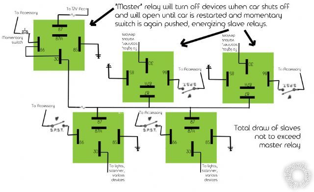
 Removed the jumper, noted that the switches get power from accessory
 )
Anyways, your diagram looks fine by me.
You can turn on any slave but they will not turn on until you manually momentarily push the "Master" momentary switch.
ACC must be on for the Master to come on.
The Master relay stays on/energised until ACC loses power.
When the Master turns off, all power is lost to the slave devices/relays.
Be aware that ACC drops when cranking. (But...)
All slaves with SPST switches turned on will turn on again once the Master is re-energised - eg, another manual push after cranking.
Oh no, stupid me. I wrote the following and then realised it's wrong because of the latching aspect - you have to turn OFF the Master Relay's power (#87) to drop it and hence slave relays/loads.
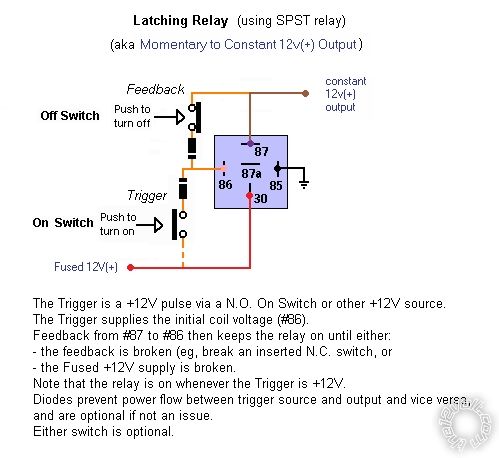
However adding a manual off as per 2nd (circuit) diagram could overcome that.
