


2 actuators, 1 switch, 2 relays or 4 relays
Home /
the12volt's Install Bay /
Car Security and Convenience / 2 actuators, 1 switch, 2 relays or 4 relays ( Topic Closed)


Posted: April 13, 2014 at 11:06 PM / IP Logged
 I plan to install speaker and power window kit, thus, I would like to reduce the number of wires running through the door.
Therefore, I prefer to add relays with 2 wires instead of using 5 wire harness that comes with the kit.
I would like to find out whether this wiring diagram is OK or not.
I plan to install speaker and power window kit, thus, I would like to reduce the number of wires running through the door.
Therefore, I prefer to add relays with 2 wires instead of using 5 wire harness that comes with the kit.
I would like to find out whether this wiring diagram is OK or not.
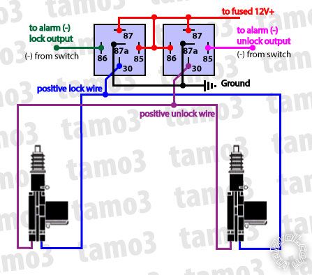 Could you help me to point out my mistake?
Thanks in advance!
tamo3
Could you help me to point out my mistake?
Thanks in advance!
tamo3
howie
(aka: harryharris)


Silver -
Posts: 355
Joined: February 17, 2014
Location: Florida, United States
Posted: April 14, 2014 at 1:10 AM / IP Logged
Posted: April 15, 2014 at 12:40 AM / IP Logged
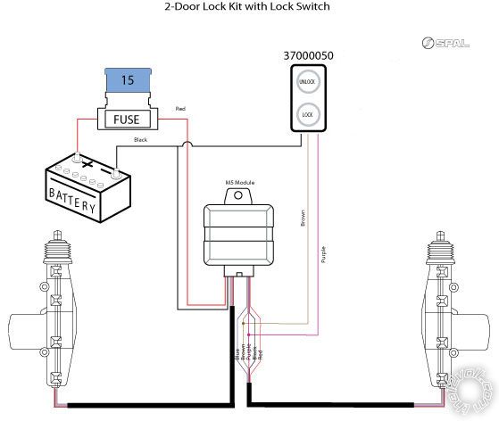
 Is the correct way to locate switch and diode?
I want to use the SPAL switch that I already purchased.
Thanks,
tamo3
SPAL Switch
Is the correct way to locate switch and diode?
I want to use the SPAL switch that I already purchased.
Thanks,
tamo3
SPAL Switch 
Posted: April 15, 2014 at 2:23 AM / IP Logged
Posted: April 15, 2014 at 2:28 AM / IP Logged
Posted: April 15, 2014 at 12:10 PM / IP Logged
Posted: April 16, 2014 at 2:40 AM / IP Logged
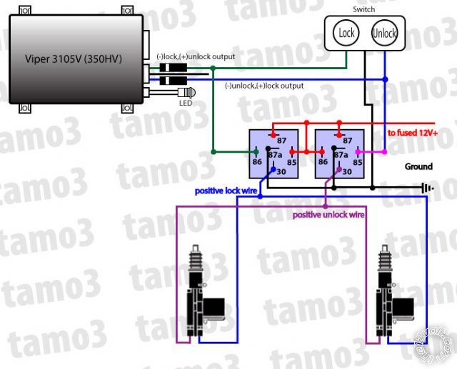
 This is what I guessed.
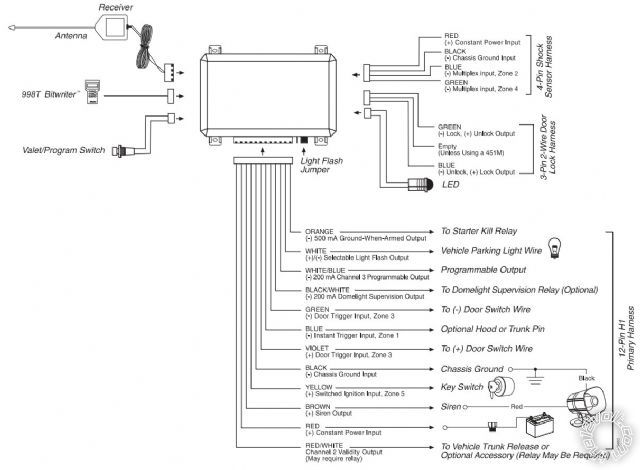 This is Viper 3105V(350V) wiring instruction.
Thanks,
tamo3
This is Viper 3105V(350V) wiring instruction.
Thanks,
tamo3Posted: April 16, 2014 at 3:00 AM / IP Logged
Posted: April 16, 2014 at 11:00 PM / IP Logged
Posted: April 21, 2014 at 11:46 AM / IP Logged
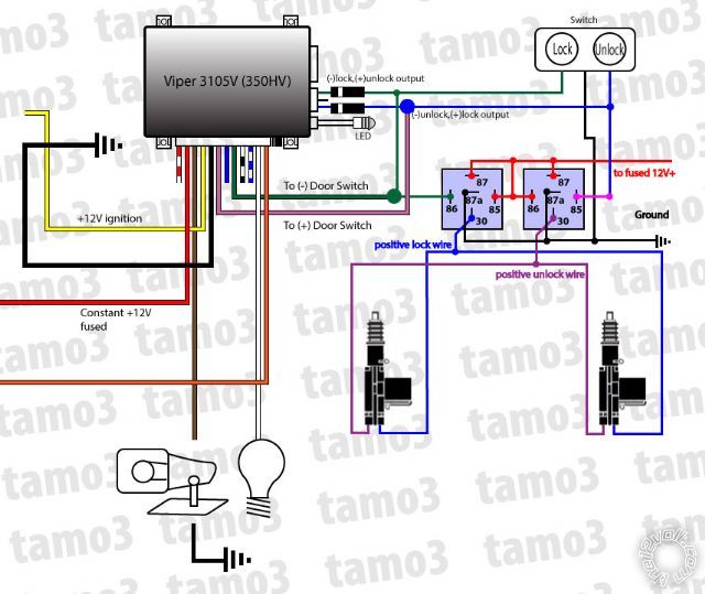
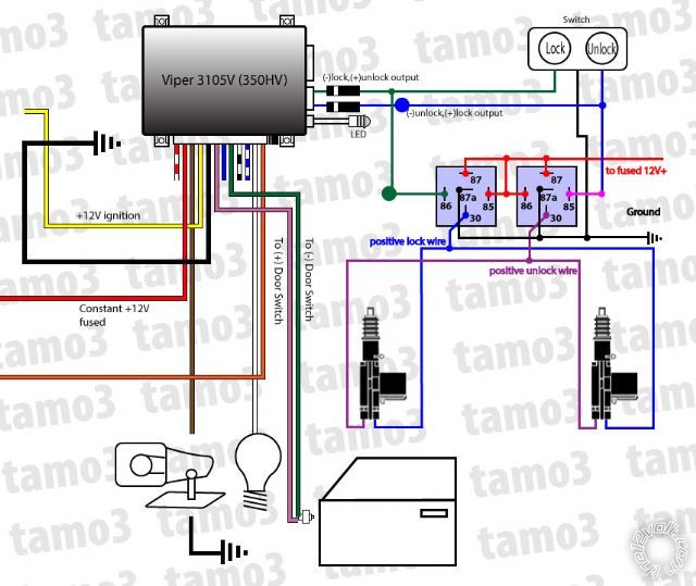 updated final diagram for the reference.
Sorry, you can NOT post a reply.
This topic is closed.
 Printable version
| You cannot post new topics in this forum You cannot reply to topics in this forum You cannot delete your posts in this forum You cannot edit your posts in this forum You cannot create polls in this forum You cannot vote in polls in this forum |

| Search the12volt.com |
Follow the12volt.com 
Monday, March 30, 2026 • Copyright © 1999-2026 the12volt.com, All Rights Reserved • Privacy Policy & Use of Cookies

Monday, March 30, 2026 • Copyright © 1999-2026 the12volt.com, All Rights Reserved • Privacy Policy & Use of Cookies
Disclaimer:
*All information on this site ( the12volt.com ) is provided "as is" without any warranty of any kind, either expressed or implied, including but not limited to fitness for a particular use. Any user assumes the entire risk as to the accuracy and use of this information. Please
verify all wire colors and diagrams before applying any information.
