


relay behavior


Posted: May 02, 2014 at 11:33 AM / IP Logged

Posted: May 02, 2014 at 3:39 PM / IP Logged
Posted: May 02, 2014 at 4:55 PM / IP Logged
Posted: May 02, 2014 at 5:15 PM / IP Logged
Posted: May 02, 2014 at 6:01 PM / IP Logged

Posted: May 02, 2014 at 7:45 PM / IP Logged

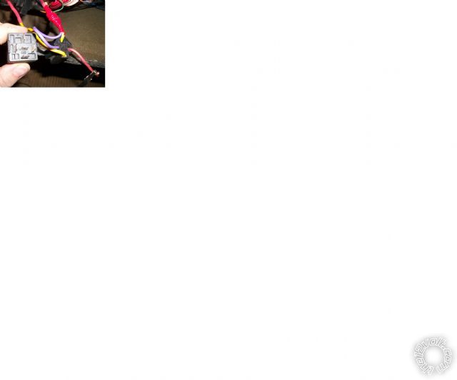 hello again, as you can see on the picture, my test light gives me a positive feedback on the red wire that is connected to the wires that are sending the signal from the alarm CPU. the cpu sends a 200MA ground signal when activated. im using this as a remote activated light. my issue is that a +12 battery voltage is sent back to the cpu of the alarm . for clarity, the yellow wire is going to the device beeing lighted up, the purple and yellow/black are fused on +12v and the red receives the signal from the alarm cpu.
thank you once again for your time.
Eric
hello again, as you can see on the picture, my test light gives me a positive feedback on the red wire that is connected to the wires that are sending the signal from the alarm CPU. the cpu sends a 200MA ground signal when activated. im using this as a remote activated light. my issue is that a +12 battery voltage is sent back to the cpu of the alarm . for clarity, the yellow wire is going to the device beeing lighted up, the purple and yellow/black are fused on +12v and the red receives the signal from the alarm cpu.
thank you once again for your time.
EricPosted: May 02, 2014 at 8:36 PM / IP Logged
Posted: May 03, 2014 at 1:50 AM / IP Logged
Posted: May 03, 2014 at 1:58 AM / IP Logged

Posted: May 03, 2014 at 2:54 AM / IP Logged
 )
) Printable version
| You cannot post new topics in this forum You cannot reply to topics in this forum You cannot delete your posts in this forum You cannot edit your posts in this forum You cannot create polls in this forum You cannot vote in polls in this forum |

| Search the12volt.com |
Follow the12volt.com 
Thursday, April 2, 2026 • Copyright © 1999-2026 the12volt.com, All Rights Reserved • Privacy Policy & Use of Cookies

Thursday, April 2, 2026 • Copyright © 1999-2026 the12volt.com, All Rights Reserved • Privacy Policy & Use of Cookies
Disclaimer:
*All information on this site ( the12volt.com ) is provided "as is" without any warranty of any kind, either expressed or implied, including but not limited to fitness for a particular use. Any user assumes the entire risk as to the accuracy and use of this information. Please
verify all wire colors and diagrams before applying any information.
