


remote starter theory
Home /
the12volt's Install Bay /
Car Security and Convenience / remote starter theory ( Topic Closed)


Posted: October 26, 2014 at 8:07 PM / IP Logged
 Now i have read several threads on this site that tell me the above is a terrible idea and that this is a more appropriate install.
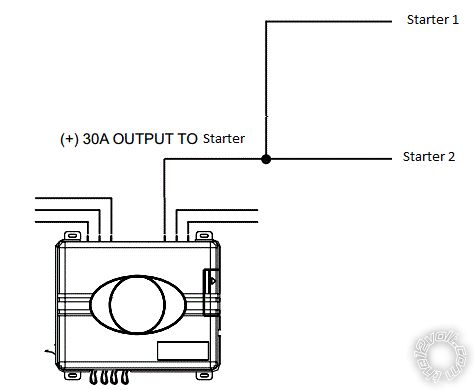
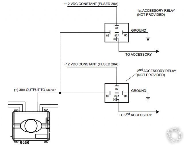 Question #1 - If the current draw of both starter wires is within the capacity of the installed relay in the remote starter why is it not ok to do what is shown in the first picture?
Question #2 - Assuming the first picture is bad why wouldn't you just install it like this since the unit is certainly designed to at least handle one of the wires.
Question #1 - If the current draw of both starter wires is within the capacity of the installed relay in the remote starter why is it not ok to do what is shown in the first picture?
Question #2 - Assuming the first picture is bad why wouldn't you just install it like this since the unit is certainly designed to at least handle one of the wires. 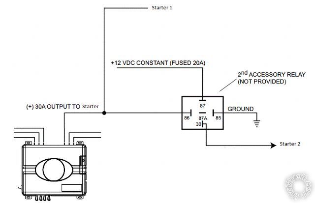 Question #3 - Most cars (including mine) only have one 12v constant wire that all of this power is being tapped from. Do most people use this wire to tap off all of these extra relays or are some people running a completely separate line from the battery? Just curious what everyone else does because this is the only one that has ever seems weird to me during installs because you can have 3 or 4 connections coming off this one 12v constant wire.
I'm chomping at the bit to hear responses to these questions.
Question #3 - Most cars (including mine) only have one 12v constant wire that all of this power is being tapped from. Do most people use this wire to tap off all of these extra relays or are some people running a completely separate line from the battery? Just curious what everyone else does because this is the only one that has ever seems weird to me during installs because you can have 3 or 4 connections coming off this one 12v constant wire.
I'm chomping at the bit to hear responses to these questions.

Posted: October 26, 2014 at 9:40 PM / IP Logged

Posted: October 26, 2014 at 10:25 PM / IP Logged
Posted: October 27, 2014 at 2:09 AM / IP Logged

Posted: October 29, 2014 at 8:25 PM / IP Logged
Sorry, you can NOT post a reply.
This topic is closed.
 Printable version
| You cannot post new topics in this forum You cannot reply to topics in this forum You cannot delete your posts in this forum You cannot edit your posts in this forum You cannot create polls in this forum You cannot vote in polls in this forum |

| Search the12volt.com |
Follow the12volt.com 
Thursday, May 14, 2026 • Copyright © 1999-2026 the12volt.com, All Rights Reserved • Privacy Policy & Use of Cookies

Thursday, May 14, 2026 • Copyright © 1999-2026 the12volt.com, All Rights Reserved • Privacy Policy & Use of Cookies
Disclaimer:
*All information on this site ( the12volt.com ) is provided "as is" without any warranty of any kind, either expressed or implied, including but not limited to fitness for a particular use. Any user assumes the entire risk as to the accuracy and use of this information. Please
verify all wire colors and diagrams before applying any information.
