the12volt.com spacer
icon

07 town & country


Post ReplyPost New Topic
< Prev Topic Next Topic >
oleg4 
Member - Posts: 40
Member spacespace
Joined: December 21, 2011
Location: United States
Posted: November 07, 2014 at 6:08 PM / IP Logged  
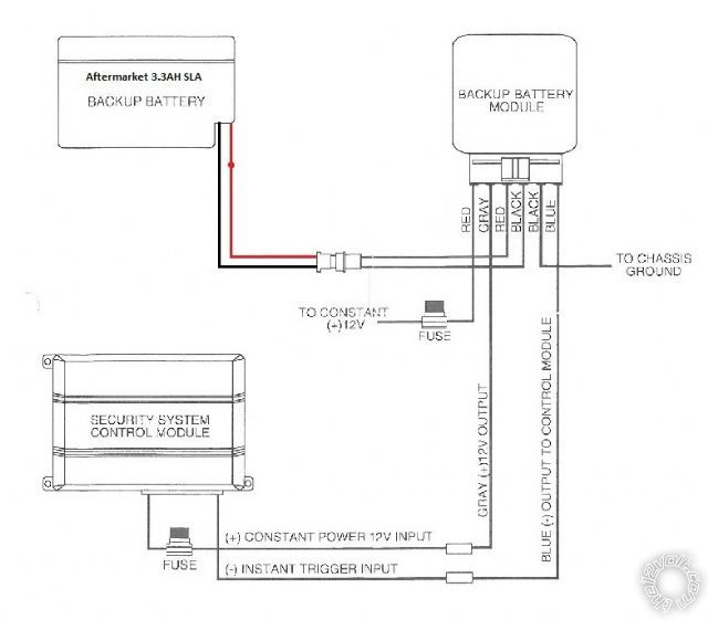
and this is how i installed my backup battery
the instant trigger is wired to 24pin aux/shut/trig harness
10 BLUE (-)TRUNK PIN/INSTANT TRIGGER INPUT (N/C OR N/O) --- Instant trigger
07 town & country - Page 2 - Last Post -- posted image.
smokeman1 
Platinum - Posts: 1,588
Platinum spaceThis member has made a donation to the12volt.com. Click here for more info.spaceThis member has been recognized as an authority in Mobile Security and Convenience. Click here for more info.spacespace
Joined: September 14, 2009
Location: Wisconsin, United States
Posted: November 07, 2014 at 6:41 PM / IP Logged  
RED / Black and Red to constant 12volt
Remove green from starter wire (yellow) and connect violet
When all else fails, Read the Instructions
Support the12volt.com Make a Donation
kreg357 
Platinum - Posts: 7,783
Platinum spaceThis member has made a donation to the12volt.com. Click here for more info.spaceThis member has been recognized as an authority in Electrical Theory. Click here for more info.spaceThis member has been recognized as an authority in Mobile Security and Convenience. Click here for more info.spacespace
Joined: January 30, 2009
Location: Pennsylvania, United States
Posted: November 07, 2014 at 6:46 PM / IP Logged  

1 NC No Connection- -   -   – - – -     -- -       – - - –      -- -        Not used

2 RED / BLACK (+) FUSED 12V ACCESSORY/STARTER INPUT        +12V Constant
3 PINK/BLACK (+) FLEX RELAY INPUT 87A FLEX RELAY- - - -       Not used
4 PINK/WHITE (+) IGNITION 2 / FLEX RELAY OUTPUT- - - - - Not used
5 RED (+) FUSED 12V IGNITION 1 INPUT    -   -   - - - - - – - - – - - -  +12V Constant
6 GREEN (+) STARTER INPUT (KEY SIDE ) -      – - - –    – - YELLOW   @ IGNITION SWITCH   ( cut wire )
7 VIOLET (+) STARTER OUTPUT (CAR SIDE ) -       – - - – - - -         Yellow     @ IGNITION SWITCH   ( cut wire )
8 ORANGE (+) ACCESSORY OUTPUT -   -   - - - - - – - - – - - - - -      Not used
9 RED / WHITE (+) FUSED 12V IGNITION 2 / FLEX RELAY INPUT      Not used
10 PINK (+) IGNITION 1 INPUT/OUTPU -   -   - - - - - – - - – - - - - -      PINK/WHITE IGNITION SWITCH

Soldering is fun!
oleg4 
Member - Posts: 40
Member spacespace
Joined: December 21, 2011
Location: United States
Posted: November 07, 2014 at 7:44 PM / IP Logged  
thx for the reply, one more question the instant trigger from the back up battery, did i connect it correctly.
this is how i connected it
24pin aux/shut/trig harness
10 BLUE (-)TRUNK PIN/INSTANT TRIGGER INPUT (N/C OR N/O) --- Instant trigger Back Up Battery
Page of 2

Sorry, you can NOT post a reply.
This topic is closed.

  Printable version Printable version Post ReplyPost New Topic
You cannot post new topics in this forum
You cannot reply to topics in this forum
You cannot delete your posts in this forum
You cannot edit your posts in this forum
You cannot create polls in this forum
You cannot vote in polls in this forum

  •  
Search the12volt.com
Follow the12volt.com Follow the12volt.com on Facebook
Saturday, April 27, 2024 • Copyright © 1999-2024 the12volt.com, All Rights Reserved Privacy Policy & Use of Cookies
Disclaimer: *All information on this site ( the12volt.com ) is provided "as is" without any warranty of any kind, either expressed or implied, including but not limited to fitness for a particular use. Any user assumes the entire risk as to the accuracy and use of this information. Please verify all wire colors and diagrams before applying any information.

Secured by Sectigo
the12volt.com spacer
Support the12volt.com
Top
the12volt.com spacer