the12volt.com spacer
icon

dodge dakota viper 5706v


Post ReplyPost New Topic
< Prev Topic Next Topic >
onthebrink18 
Member - Posts: 3
Member spacespace
Joined: November 30, 2014
Location: Missouri, United States
Posted: December 07, 2014 at 5:00 PM / IP Logged  
I am attempting to install my first remote start system into my 2008 Dodge Dakota. The remote starter/alarm is the Viper 5706V, and will be connected using the DBALL2. I think that I have all of the connections figured out, but I would like a double check from the local experts dodge dakota viper 5706v -- posted image.
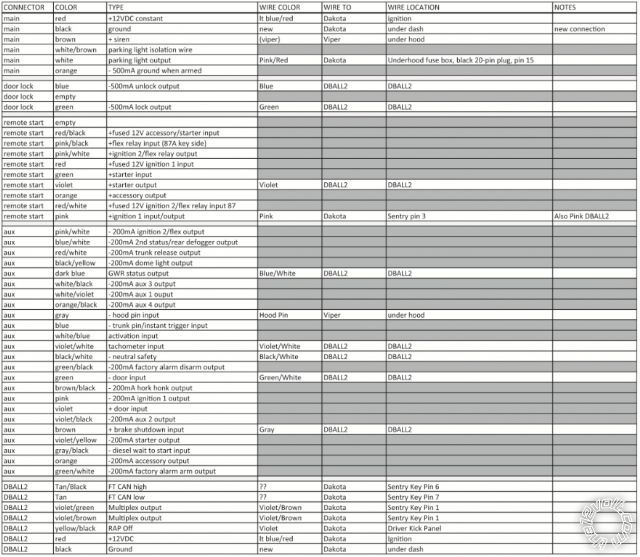
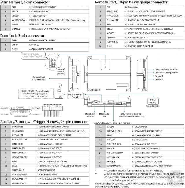
. I have read about issues in using the D2D method and I have decided on using W2W. The wires that I am most confused about are the 10-pin heavy gauge wires on the Viper module.
The dark gray lines are not connected.
dodge dakota viper 5706v -- posted image.
kreg357 
Platinum - Posts: 7,783
Platinum spaceThis member has made a donation to the12volt.com. Click here for more info.spaceThis member has been recognized as an authority in Electrical Theory. Click here for more info.spaceThis member has been recognized as an authority in Mobile Security and Convenience. Click here for more info.spacespace
Joined: January 30, 2009
Location: Pennsylvania, United States
Posted: December 07, 2014 at 5:28 PM / IP Logged  

Looks good!  Only one oversight.  You will need to connect the thick Pin 5 Red and Pin 2 RED / Black wire to +12V constant.

I wouldn't use the +12V at the ignition switch harness.  It would be better to get all your power from here :
12volts    Red  (+)    battery or IPM **
** The IPM (Integrated Power Module) is in the engine compartment, on the driver fender.

Here are the wire color of the CAN wires at the igntion harness :

CanHigh      pin 6 WHITE/ Orange (DATA)         @ Ignition switch
CanLow       pin 7 White (DATA)          @ Ignition switch

Soldering is fun!
onthebrink18 
Member - Posts: 3
Member spacespace
Joined: November 30, 2014
Location: Missouri, United States
Posted: December 07, 2014 at 6:18 PM / IP Logged  
Thank you for the fast replydodge dakota viper 5706v -- posted image.. I will make those changes.
Would it make sense to use a pick and remove the unused pins from the connector housing, or should I leave them in for proper connector retention and just tape the ends off?
kreg357 
Platinum - Posts: 7,783
Platinum spaceThis member has made a donation to the12volt.com. Click here for more info.spaceThis member has been recognized as an authority in Electrical Theory. Click here for more info.spaceThis member has been recognized as an authority in Mobile Security and Convenience. Click here for more info.spacespace
Joined: January 30, 2009
Location: Pennsylvania, United States
Posted: December 07, 2014 at 6:32 PM / IP Logged  

De-pinning is a pain but makes things look neat.  The down side is that if you ever need to make a change, you have nothing to work with.  I make a compromise between the two and just cut the unused wires to a bit less than 2 inches, then group them together with heat shrink tubing that covers the ends and, after heating, holds them securely.  If I ever need to make a change, I have enough wire to solder on a length of the correct color / gauge wire.  Think most installers have a large bag of trimmed ends for adding length to any wire during an install to reach the destination.

Soldering is fun!
onthebrink18 
Member - Posts: 3
Member spacespace
Joined: November 30, 2014
Location: Missouri, United States
Posted: December 07, 2014 at 6:38 PM / IP Logged  
That sounds like a good compromise.

Sorry, you can NOT post a reply.
This topic is closed.

  Printable version Printable version Post ReplyPost New Topic
You cannot post new topics in this forum
You cannot reply to topics in this forum
You cannot delete your posts in this forum
You cannot edit your posts in this forum
You cannot create polls in this forum
You cannot vote in polls in this forum

  •  
Search the12volt.com
Follow the12volt.com Follow the12volt.com on Facebook
Friday, April 19, 2024 • Copyright © 1999-2024 the12volt.com, All Rights Reserved Privacy Policy & Use of Cookies
Disclaimer: *All information on this site ( the12volt.com ) is provided "as is" without any warranty of any kind, either expressed or implied, including but not limited to fitness for a particular use. Any user assumes the entire risk as to the accuracy and use of this information. Please verify all wire colors and diagrams before applying any information.

Secured by Sectigo
the12volt.com spacer
Support the12volt.com
Top
the12volt.com spacer