the12volt.com spacer
icon

dorman seat heater


Post ReplyPost New Topic
< Prev Topic Next Topic >
samhunter1 
Member - Posts: 2
Member spacespace
Joined: January 14, 2015
Location: Alabama, United States
Posted: January 14, 2015 at 4:05 PM / IP Logged  

have installed a Dorman seat heater in a Jeep Wrangler. The passenger’s side works as advertised. The driver’s side will work on high as it should, but on low which uses a relay in the circuit it will not disengage the relay when the switch is turned back to off. I am not sure how to post the relay diagram here, but you can search Dorman seat heater installation instructions to see the diagram. Any ideas on why the relay will not disengage? They are sending me a new harness, but I don’t know how long it will take.

Thanks,

Mark

shafferny 
Copper - Posts: 240
Copper spacespace
Joined: February 02, 2008
Location: New York, United States
Posted: January 14, 2015 at 5:26 PM / IP Logged  
Have you tried swapping the relay on the passengers side to the drivers side to see if the problem follows to the other side? You could try the same logic with the switch.
shark mobile 
Copper - Posts: 83
Copper spacespace
Joined: November 22, 2014
Location: Ontario, Canada
Posted: January 14, 2015 at 7:35 PM / IP Logged  
Most seat heaters use Common five pin relays...Swapping out the relays though is a brilliant idea!
Solder, tape, repeat!
oldspark 
Gold - Posts: 4,913
Gold spacespace
Joined: November 03, 2008
Location: Australia
Posted: January 14, 2015 at 8:04 PM / IP Logged  
Agreed! (One of my initial test strategies is to rotate fuses & relays. Hence also my desire to only require a spare SPDT relay...)
Or course I'd probably use the switch's Hi to energrise the relay and carry the current for the Back heater (87 to GROUND; 86 to Hi; disconnect 87a), but if the currents are low - but then why the need for the relay? - just Ground the Common Back/Cushion junction and have Lo +12V power the Cushion on both Hi & Lo, and Hi +12V power the Back. Discard the G unless it's a illuminated switch. If it isn't the correct switch for that, why supply one with such a complicated or trouble-prone circuit?
davep. 
Gold - Posts: 641
Gold spacespace
Joined: May 27, 2011
Location: California, United States
Posted: January 14, 2015 at 9:25 PM / IP Logged  
oldspark wrote:
- but then why the need for the relay? - just Ground the Common Back/Cushion junction and have Lo +12V power the Cushion on both Hi & Lo, and Hi +12V power the Back. Discard the G unless it's a illuminated switch. If it isn't the correct switch for that, why supply one with such a complicated or trouble-prone circuit?
Look at that diagram again, OldDude. You missed how it works. Both elements are powered in both positions, not just one element for Lo. The relay puts the two elements in SERIES for "lo". The switch carries the full current for both heating positions.
The Ground on the switch must be for an indicator. The switch only switches power for both levels.
Again, the relay switches the elements from parallel (HIGH) to series (LOW). Pretty simple the way it is, IMO.
davep. 
Gold - Posts: 641
Gold spacespace
Joined: May 27, 2011
Location: California, United States
Posted: January 14, 2015 at 9:32 PM / IP Logged  
samhunter1 wrote:
it will not disengage the relay when the switch is turned back to off...... Any ideas on why the relay will not disengage?
The Power and HI terminals on the switch are reversed. Switch those two wires, and I bet it will work.
EDIT: It may not be these exact two wires, but it is probably a mis-connected pair of wires at either the relay or the switch. Compare the malfunctioning side to the 'good' side.
Does the switch have an indicator for each level? Ie, two bulbs? If so, another possibility is if the ground at the switch for the indicator is open. This would hold the relay on even after the switch was turned off.
Thanks for posting this. I learned a few things.
oldspark 
Gold - Posts: 4,913
Gold spacespace
Joined: November 03, 2008
Location: Australia
Posted: January 14, 2015 at 10:04 PM / IP Logged  
davep. wrote:
The relay puts the two elements in SERIES for "lo".
With the two "negatives" hard bonded to GND? I think not - the centre link to GND would have to be broken and each other element end to +12V and GND respectively (as done for some head- or bright-lights as DRLs or parkers etc).
FYI - this is the diagram I am working off:
dorman seat heater -- posted image.
davep. 
Gold - Posts: 641
Gold spacespace
Joined: May 27, 2011
Location: California, United States
Posted: January 14, 2015 at 10:13 PM / IP Logged  
oldspark wrote:
davep. wrote:
The relay puts the two elements in SERIES for "lo".
With the two "negatives" hard bonded to GND?   
But they are NOT "hard bonded to ground".
Look again. The two elements are common to each other, and to the "HI" terminal on the switch.
When in LO, the relay is energized, Power is available at 87, goes through the BACK through the common connection into the SEAT cushion and to ground. The two elements are in series in LO.
The HI terminal at the switch is N/C to anything in LO.
davep. 
Gold - Posts: 641
Gold spacespace
Joined: May 27, 2011
Location: California, United States
Posted: January 14, 2015 at 10:23 PM / IP Logged  
Here. See if this helps. Power flow in LO.
dorman seat heater -- posted image.
Power flow in HIGH:
dorman seat heater -- posted image.
oldspark 
Gold - Posts: 4,913
Gold spacespace
Joined: November 03, 2008
Location: Australia
Posted: January 14, 2015 at 10:31 PM / IP Logged  
Ooops!! dorman seat heater -- posted image. 
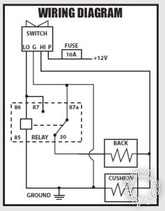
My bad! Even if I did misread the series operation, htf could I miss the GND point - it is NOT their common!? dorman seat heater -- posted image.
And therefor my "preferred" wiring is crap - the normal relay-only power switching requires SPDT & SPST (DPDT) contacts. For headlights etc yes, but not low current applications where a suitable switch is available.
Sorry for that.
I'll bug out - I agree with davep's incorrect wiring reply.
Page of 2

  Printable version Printable version Post ReplyPost New Topic
You cannot post new topics in this forum
You cannot reply to topics in this forum
You cannot delete your posts in this forum
You cannot edit your posts in this forum
You cannot create polls in this forum
You cannot vote in polls in this forum

  •  
Search the12volt.com
Follow the12volt.com Follow the12volt.com on Facebook
Wednesday, April 24, 2024 • Copyright © 1999-2024 the12volt.com, All Rights Reserved Privacy Policy & Use of Cookies
Disclaimer: *All information on this site ( the12volt.com ) is provided "as is" without any warranty of any kind, either expressed or implied, including but not limited to fitness for a particular use. Any user assumes the entire risk as to the accuracy and use of this information. Please verify all wire colors and diagrams before applying any information.

Secured by Sectigo
the12volt.com spacer
Support the12volt.com
Top
the12volt.com spacer