No problem. Thanks for the added info.
I'll rule out conversion of cig-socket phone charges etc. (I've done a few for 3V but it involves changing one resistor.)
Any idea of the current involved? It's probably not much since it/they run off batteries and hence most (voltage) regulators should handle them.
If you have a DMM or equivalent you could measure the current. If not, you'll need one to adjust the regulator output voltage(s). Sure, you could borrow one, but then how will you check your solar array... is
it overcharging or is the battery about to die..?
The above might be options we discuss later.
Switching SMPS voltage regulators...
Tho these giddammit small modern techno "switching" power converters may seem complex, they are almost always cheaper than their old
analog counterparts and few would use anything else.
However you said
solar and hence IMO they are essential - switching regulators use about 1/4 the power of linear types for a 12V to 3V conversion system.
Did I say small? How's about...
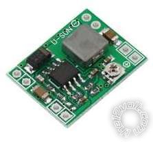
... a thumbnail-sized 3 Amp step-down voltage regulator - eg eBay item 291353891841 (for $1 each???). I've used a few....
Until I considered the LED current I considered these for you...
(eg, eBay items 321432207998 221549737814 221670472408 or
DHGate.)
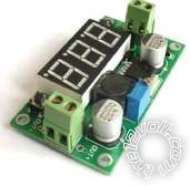
Their big advantage is the multiturn adjustment pot (potentiometer = variable resistor) making it so much easier to adjust (try getting an accurate output voltage with those small trimpots in the earlier pic! .. and ensuring it isn't knocked or vibrated).
Another advantage is their screw terminals - no need to solder wires or connectors.
Their 3rd advantage of being able to adjust and check the output voltage using the 3-digit voltmeter (which can also read the input voltage) is their disadvantage for power-critical situations like small solar - unless the meter can be turned off when not required. (I reckon most of its ~20mA "standby" current is due to the display.)
But finding a step-down switching converter (ie, NOT 337 or LM337 types!) with multiturn trimpot and screw terminals and NO voltmeter appears tricky...
However I did find...
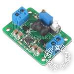
(eBay item 280751515397, but see also
dealextremes' offering.)
Or...
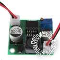
(ebay 121171591143)
... which has connectors.
Are these too DIY for you - would you prefer off the shelf boxed items etc?
Most of the units above feature good over-current protection and at least some have reverse polarity protection.
If you see one with a heatsink make sure it's not a linear type (they'll need the heatsink because whatever power your timers use, the regulator will put out at least 3x as much power as waste heat).
Those
switching regulators usually do not have heatsinks tho they can be added for high currents (typically above 2A output).
Housing them can be a PITA - I always reckon the mechanicals of an electric/electronic project is the worst or most tedious part.
But I mounted my "micro" regulator (first pic above) in the engine bay. Tho I conformal coated (sprayed) the unit (except for its trimpot) I merely wrapped it in electrical tape and had is
dangling in the engine bay. Tho it did cease to work after a high-pressure engine-bay clean, it came good later. (FYI - I was using it as the
tail light voltage to my
3rd brakelight LED bar.)
BTW - I'd suggest buying a few.. Since IMO they are so cheap it's worth having at least one spare if not a few for later projects.
Anyway, your thoughts?


 Printable version


