


2005-2010 Chevrolet Cobalt Pictorial
Home /
the12volt's Install Bay /
Car Security and Convenience - Alarm/Remote Start Pictorials / 2005-2010 Chevrolet Cobalt Pictorial ( Topic Closed)


Posted: March 10, 2015 at 12:19 PM / IP Logged
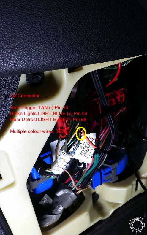
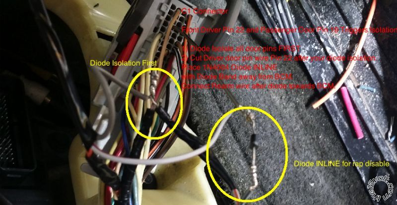
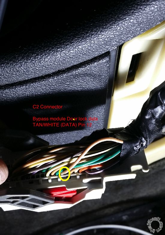
 Make sure you solder your diodes, as wrapping wire around solid metal is a poor connection. Diodes will create a "Y" where the 2 ends are the diode bands.
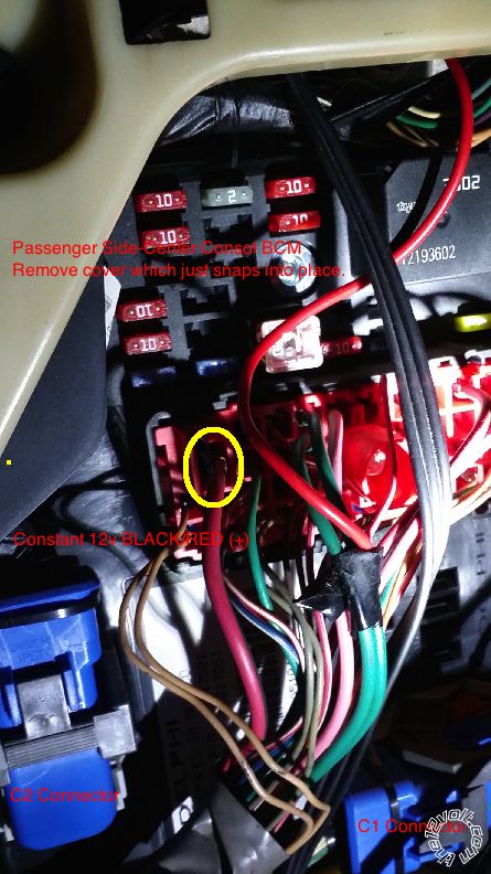
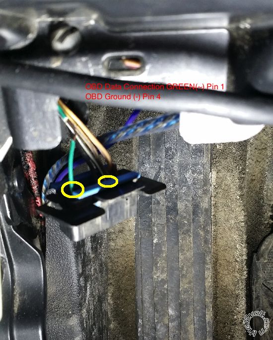
 Above the OBD is a black harness. Look for a Yellow (+) wire, which is your clutch bypass. Connect your remote starter output to this wire. Get your ground from the ODB as well. Pin 4 is a direct connection to chassis ground.
 After all connections are complete:
1) Program remotes to the unit (of not pre-programmed)
2) Close all doors, Open driver door to wake up bcm and proceed to bypass programming.
3) Program tach to the unit
4) Test system, pack it up and enjoy.
After all connections are complete:
1) Program remotes to the unit (of not pre-programmed)
2) Close all doors, Open driver door to wake up bcm and proceed to bypass programming.
3) Program tach to the unit
4) Test system, pack it up and enjoy.

Posted: March 11, 2015 at 7:57 AM / IP Logged

Sorry, you can NOT post a reply.
This topic is closed.
 Printable version
| You cannot post new topics in this forum You cannot reply to topics in this forum You cannot delete your posts in this forum You cannot edit your posts in this forum You cannot create polls in this forum You cannot vote in polls in this forum |

| Search the12volt.com |
Follow the12volt.com 
Saturday, May 23, 2026 • Copyright © 1999-2026 the12volt.com, All Rights Reserved • Privacy Policy & Use of Cookies

Saturday, May 23, 2026 • Copyright © 1999-2026 the12volt.com, All Rights Reserved • Privacy Policy & Use of Cookies
Disclaimer:
*All information on this site ( the12volt.com ) is provided "as is" without any warranty of any kind, either expressed or implied, including but not limited to fitness for a particular use. Any user assumes the entire risk as to the accuracy and use of this information. Please
verify all wire colors and diagrams before applying any information.
