the12volt.com spacer
icon

Diagram for 2 Devices with 1 Switch


Post ReplyPost New Topic
< Prev Topic Next Topic >
wiker man 
Member - Posts: 6
Member spacespace
Joined: December 22, 2013
Posted: April 23, 2015 at 6:46 AM / IP Logged  
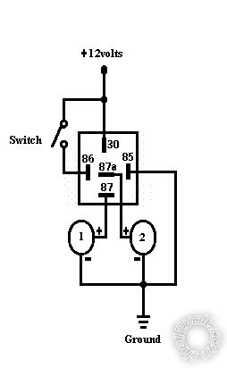
Hi, I need some help with this simple thing I am trying to do but too worked up to figure out myself. I am going to be using a simple on off switch, 12V. When on, it will complete a circuit / provide 12V to a device which will activate. But at the same time I am wanting to hook another device to it, which as soon as its pressed on will turn off.
So when Switch is On. #1 Device is On and #2 Device is Off, and when Switch is off, I want #1 Device to Turn off while #2 Device turns on.
Diagram for 2 Devices with 1 Switch -- posted image.
howie ll 
Pot Metal - Posts: 16,466
Pot Metal spacespace
Joined: January 09, 2007
Location: United Kingdom
Posted: April 23, 2015 at 10:45 AM / IP Logged  
Power to each then use a SPCO (Single Pole Change Over) switch to switch the ground side.
wiker man 
Member - Posts: 6
Member spacespace
Joined: December 22, 2013
Posted: April 23, 2015 at 3:57 PM / IP Logged  
will you draw me a diagram please ? and can it be done with relays?
wiker man 
Member - Posts: 6
Member spacespace
Joined: December 22, 2013
Posted: April 23, 2015 at 3:58 PM / IP Logged  
I actually have a spesific on off switch which is on/off only, not SPCO and I rather use that. thanks.
the12volt 
Administrator - Posts: 3,955
Administrator spaceThis member has made a donation to the12volt.com. Click here for more info.spaceThis member has been recognized as an authority in Electrical Theory. Click here for more info.spaceThis member has been recognized as an authority in Mobile Audio and Video. Click here for more info.spaceThis member has been recognized as an authority in Mobile Security and Convenience. Click here for more info.spacespace
Joined: March 07, 2002
Location: Louisiana, United States
Posted: April 23, 2015 at 4:48 PM / IP Logged  
One side of switch to ground.
Other side of switch to terminal 86 of an SPDT relay.
Fused 12V+ to terminals 85 and 30 of SPDT relay.
Terminal 87 of SPDT relay to device 1 power.
Terminal 87a of SPDT relay to device 2 power.
Both device grounds to ground.
Diagram for 2 Devices with 1 Switch -- posted image. the12volt • Support the12volt.com
hotwaterwizard 
Silver - Posts: 1,350
Silver spacespace
Joined: December 11, 2003
Location: California, United States
Posted: April 25, 2015 at 10:38 PM / IP Logged  
Here you go!Diagram for 2 Devices with 1 Switch -- posted image.
John DeRosa (Hotwaterwizard)
Stockton California
When in doubt, try it out !
howie ll 
Pot Metal - Posts: 16,466
Pot Metal spacespace
Joined: January 09, 2007
Location: United Kingdom
Posted: April 26, 2015 at 4:18 AM / IP Logged  
Cynical me would like to question both of the above answers in light of the fact that we didn't inquire the purpose of the circuit, is it in an auto and therefore will one circuit be on all of the time? That's why I recommended a centre off switch.
hotwaterwizard 
Silver - Posts: 1,350
Silver spacespace
Joined: December 11, 2003
Location: California, United States
Posted: April 26, 2015 at 8:20 PM / IP Logged  
True we don't know the application. I read the post several times to come up with this solution.
John DeRosa (Hotwaterwizard)
Stockton California
When in doubt, try it out !
howie ll 
Pot Metal - Posts: 16,466
Pot Metal spacespace
Joined: January 09, 2007
Location: United Kingdom
Posted: April 27, 2015 at 3:07 AM / IP Logged  
Yes, let's hope the 12V+ source is ignition switched.
hotwaterwizard 
Silver - Posts: 1,350
Silver spacespace
Joined: December 11, 2003
Location: California, United States
Posted: April 27, 2015 at 9:24 PM / IP Logged  
switched and fused.
John DeRosa (Hotwaterwizard)
Stockton California
When in doubt, try it out !
Page of 2

  Printable version Printable version Post ReplyPost New Topic
You cannot post new topics in this forum
You cannot reply to topics in this forum
You cannot delete your posts in this forum
You cannot edit your posts in this forum
You cannot create polls in this forum
You cannot vote in polls in this forum

  •  
Search the12volt.com
Follow the12volt.com Follow the12volt.com on Facebook
Friday, April 19, 2024 • Copyright © 1999-2024 the12volt.com, All Rights Reserved Privacy Policy & Use of Cookies
Disclaimer: *All information on this site ( the12volt.com ) is provided "as is" without any warranty of any kind, either expressed or implied, including but not limited to fitness for a particular use. Any user assumes the entire risk as to the accuracy and use of this information. Please verify all wire colors and diagrams before applying any information.

Secured by Sectigo
the12volt.com spacer
Support the12volt.com
Top
the12volt.com spacer