I very much appreciate your help. which I find it is: rap off : yellow / black dball2 not know where , if where it is ( - ) driver door trigger. Thanks for your great help kreg357 ; and howie ll.
Here I put a list according to their suggestions and assistance , if it is wrong correct me . I am grateful to God your help pay much they are at work and there abound them a hundredfold.
thank you very much .
1. Jeep compass sport 2014
2. Viper 5906V
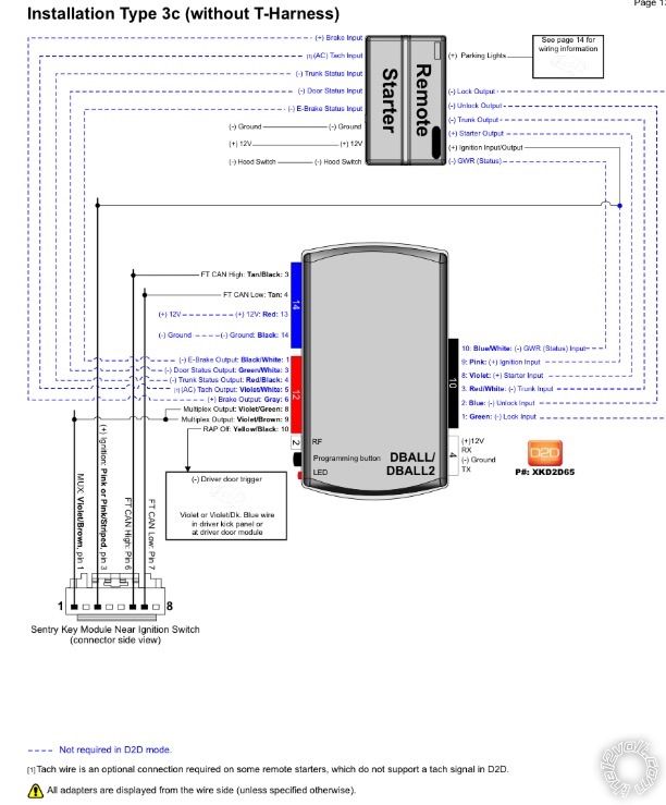
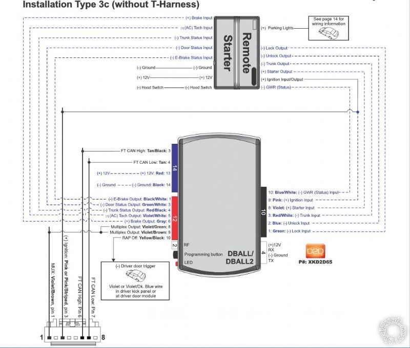
3. Dball2
Going with W2W between the Viper & Dball2
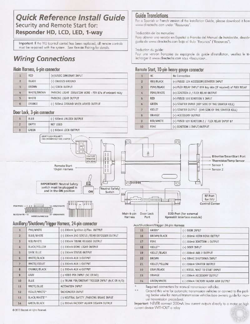
Viper 5906V H3
H3/1 NC No Connection Not Used
H3/2 RED / BLACK (+) FUSED 12V ACC/STARTER INPUT + 12 constant
H3/3 PINK/BLACK (+) FLEX RELAY INPUT 87A Not Used
H3/4 PINK/WHITE (+) IGNITION 2 / FLEX RELAY OUTPUT not use
H3/5 RED (+) FUSED 12V IGNITION 1 INPUT +12V constant
H3/6 GREEN (+) STARTER INPUT (KEY SIDE) not use
H3/7 VIOLET (+) STARTER OUTPUT (CAR SIDE) violet (+) @ starter input, pin plug, pin 8 dball2.
H3/8 ORANGE (+) ACCESSORY OUTPUT not use
H3/9 RED / WHITE (+) FUSED 12V IGNITION 2 / FLEX RELAY not use
H3/10 PINK (+) IGNITION 1 INPUT/OUTPUT Pink (+) @ ignition input, pin 9, dball2
Here is the Viper H2 connections :
Viper 5906v Harness 2
AUX/Shutdown/Trigger, 24-pin
H2/1 (-) Ignition 2 / Flex Output .2A Pink/White Not Used
H2/2 (-) 2nd Status / Rear Defogger Output .2A Blue/White Not Used
H2/3 (-) Trunk Release Output .2A RED / White To Dball2 RED / White (-) pin 3, pin plug 10
H2/4 (-) Dome Light Output .2A BLACK / YELLOW Not Used
H2/5 (-) Status Output .2A Dark Blue To Dball2 (-) GWR (status) Blue/White pin 10, pin plug 10
H2/6 (-) Aux 3 Output .2A WHITE/ BlackNot Used
H2/7 (-) Aux 1 Output .2A WHITE/ VioletNot Used
H2/8 (-) Aux 4 Output .2A ORANGE / Black Not Used
H2/9 (-) Hood Pin Input (Normally On or Normally Off) Gray not use
H2/10 (-) Trunk Pin / Instant Trigger Input Blue To Dball2 (-) trunk status output RED / black pin 4. 12 pin Plug
H2/11 Activation Input WHITE/ Blue Not Used
H2/12 Tachometer Input Violet/White To dball2 ac tach output violet/white pin 5, pin plug 12
H2/13 (-) Neutral Safety / Parking Brake Input BLACK/ White To Chassis Ground ****
H2/14 (-) Factory Alarm Disarm Output .2A GREEN/ Black Not Used
H2/15 (-) Door Input Green To Dball2 (-) door status output GREEN / WHITE pin 3. Pin plug 12
H2/16 (-) Horn Honk Output .2A BROWN / Black not use
H2/17 (-) Ignition 1 Output .2A Pink Not Used
H2/18 (+) Door Input Violet Not Used
H2/19 (-) Aux 2 Output.2A Violet/Black Not Used
H2/20 (+) Brake Shutdown Input BrownTo Dball2 (+) brake output gray pin 6, pin plug 12
H2/21 (-) Starter Output .2A Violet / YELLOW Not Used
H2/22 (-) Diesel Wait to Start Input Gray/Black Not Used
H2/23 (-) Accessory Output .2A OrangeNot Used
H2/24 (-) Factory Alarm Arm Output .2A GREEN / WHITE Not Used
All that is left is the H1 harness :
Main Harness (H1), 6-pin connector
H1/1 RED (+)12VDC CONSTANT INPUT 12 constant
H1/2 BLACK (-) CHASSIS GROUND Chassis Ground
H1/3 BROWN (+) SIREN OUTPUT Viper siren
H1/4 WHITE/ BROWN PARKING LIGHT ISOLATION Not Used
H1/5 WHITE PARKING LIGHT OUTPUT not use
H1/6 ORANGE (-) 500mA GWA OUTPUT Not Used
Here are two 529t , you want to install
529t power windows module
Blue motor side 1
Gray (-) output through activation, side 1
Brown switch side 1
Orange (-) activation input side 1. go to viper h1/6 orange
Black (-) chassis ground
Gray/black (-) output through activation side 2
Red (+) constant
ORANGE / black (-) activation input side 2. go to viper h1/6 orange
Green motor, side 2
White switch side 2
I have two 529t , and do not know where it goes : the gray wire ?.


 parking ligth if I can use 4 or 5 {Main Harses wire, 6-pin connector}, you can tell me ?.
I need also activate when the car alarm is activated, the open windows are automatically closed.
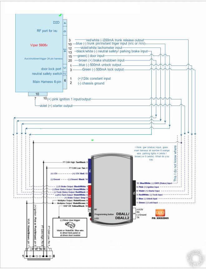
I want to know if the diagram for my car is good as well, with wires going from dball2 to viper5906v.It is corecto. I want to know who tell me ?. so I put the images, one is dball2: two wires diagram I have done: three is viper5906v wires. tell me if there is anything more to add, please thank you very much GOD BLESS YOU PEACE AND WELL.
parking ligth if I can use 4 or 5 {Main Harses wire, 6-pin connector}, you can tell me ?.
I need also activate when the car alarm is activated, the open windows are automatically closed.
I want to know if the diagram for my car is good as well, with wires going from dball2 to viper5906v.It is corecto. I want to know who tell me ?. so I put the images, one is dball2: two wires diagram I have done: three is viper5906v wires. tell me if there is anything more to add, please thank you very much GOD BLESS YOU PEACE AND WELL.


 Printable version


