the12volt.com spacer
icon

Door lock unlock


Post ReplyPost New Topic
< Prev Topic Next Topic >
kreyzie 
Member - Posts: 22
Member spacespace
Joined: March 26, 2015
Location: Hong Kong
Posted: September 26, 2015 at 9:23 AM / IP Logged Link to Post Post Reply Quote kreyzie
Attached 3 picture for ref..
im trying to connect viper 5706 to my colt..
First Pic
Door lock unlock -- posted image.
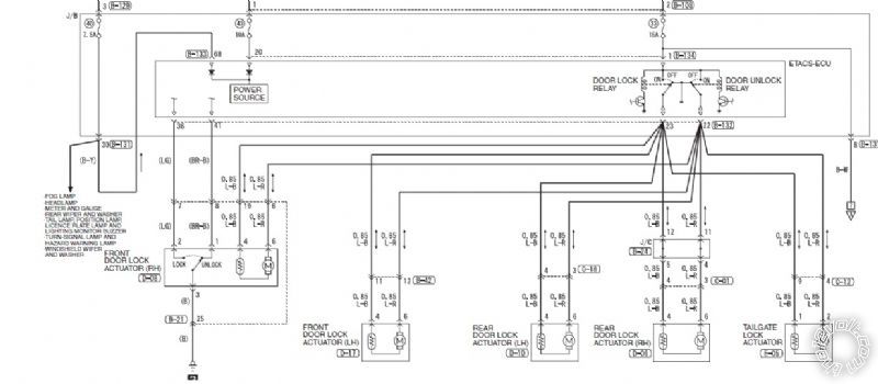
Stock circuit diagram for door lock
Second Pic
Door lock unlock -- posted image.
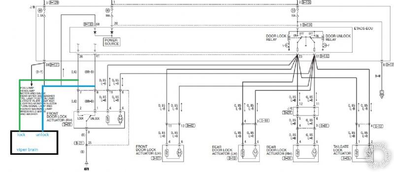
ive connect viper lock unlock wire to the door lock unlock signal wire from the door keyhole.. but lock unlock via viper fob wont work.
Third pic
Door lock unlock -- posted image.
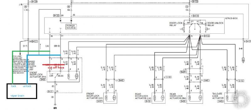
once i cut off the lock unlock signal wire before the brain , it worked..but now this is the real problem.. if i wanna lock the door while driving , the door will only lock for the driver side...same with unlock...ive tried diode it...wont work too...
howie ll 
Pot Metal - Posts: 16,466
Pot Metal spacespace
Joined: January 09, 2007
Location: United Kingdom
Posted: September 26, 2015 at 12:59 PM / IP Logged Link to Post Post Reply Quote howie ll
Add a 451 or a pair of relays and break into the motor wires at 22 and 23.
kreyzie 
Member - Posts: 22
Member spacespace
Joined: March 26, 2015
Location: Hong Kong
Posted: September 27, 2015 at 10:40 AM / IP Logged Link to Post Post Reply Quote kreyzie
thought so but just wanna confirm this wont work? if so then i have no choice to use 2 relays... i just dont understand why lock unlock manually by key works and tap into thr 2 ground wont work..
davep. 
Gold - Posts: 641
Gold spacespace
Joined: May 27, 2011
Location: California, United States
Posted: September 27, 2015 at 1:10 PM / IP Logged Link to Post Post Reply Quote davep.

You have to interrupt the unlock wire. It is grounded at all times. The switch removes the ground to unlock.

Use 2 relays.

Cut the UNLOCK brn/blu wire in two.

#87a = one of the cut brn/blu wires

#30 = the other cut brn/blu wires. (which one doesn't matter).

#85 = Viper blue unlock wire. Put a diode in this wire, band towards the Viper. ALSO the Viper green lock wire. Put a diode in this wire, band towards Viper. ( Both Viper lock and unlock wires activate this relay, but the diodes don't back-feed the lock wire.

#86 = B+, hot at all times.

Cut the lock wire in two.

#30 = the wire that goes to the module

#87a the wire that goes to the switch

#87 = Ground

#86 = Hot at all times.

#85 = Viper green lock wire. Put a diode in this wire, band towards Viper.

This should work, if the diagram is correct for your car. Easier than interfacing with the lock wires at the module, or a lock module that you probably don't have onhand in Hong Kong. Please report back if it did or didn't work. Thanks.

howie ll 
Pot Metal - Posts: 16,466
Pot Metal spacespace
Joined: January 09, 2007
Location: United Kingdom
Posted: September 27, 2015 at 1:13 PM / IP Logged Link to Post Post Reply Quote howie ll
Thanks Dave my old eyes should have looked harder!
Many Nissans and Mitz FTO used this system, aka one wire open circuit.
davep. 
Gold - Posts: 641
Gold spacespace
Joined: May 27, 2011
Location: California, United States
Posted: September 27, 2015 at 1:31 PM / IP Logged Link to Post Post Reply Quote davep.

howie ll wrote:
Thanks Dave my old eyes should have looked harder!
Many Nissans and Mitz FTO used this system, aka one wire open circuit.

Hi Howie. I edited my post. Look at the door switch again. It has to remove the ground for lock as well. So double-check my suggestion. I think I got it right. (I did leave off the anti-spike "Howie Diodes".  I don't want to confuse him yet).

howie ll 
Pot Metal - Posts: 16,466
Pot Metal spacespace
Joined: January 09, 2007
Location: United Kingdom
Posted: September 27, 2015 at 1:37 PM / IP Logged Link to Post Post Reply Quote howie ll
I wish I could Facebook "LIKE" your post that's why I played safe and suggested a pair of relays on the motor wires.
kreyzie 
Member - Posts: 22
Member spacespace
Joined: March 26, 2015
Location: Hong Kong
Posted: September 27, 2015 at 1:54 PM / IP Logged Link to Post Post Reply Quote kreyzie
my cars wiring color , sockrt number and pin number match exactly what shown in the diagram... thx dave n howie...will give it a try next morning...
davep. 
Gold - Posts: 641
Gold spacespace
Joined: May 27, 2011
Location: California, United States
Posted: September 27, 2015 at 1:57 PM / IP Logged Link to Post Post Reply Quote davep.

I looked at this again. It's a "Central Locking System" where the control switch is incorporated into the driver's lock actuator. We don't have these in North America, so I'm unfamiliar with them. It looks like the switch changes state depending on whether the lock actuator is locked or unlocked. So when the actuator mechanically changes state, the locks follow.

It may not be possible to do it with the signal wires. Howie's way, using the lock motor wires will work every time. Personally, I'd experiment with the signal wires and try to figure it out. But going for the motor wires, or using a module will work for sure.

Regards, Howie.

kreyzie 
Member - Posts: 22
Member spacespace
Joined: March 26, 2015
Location: Hong Kong
Posted: September 28, 2015 at 8:55 PM / IP Logged Link to Post Post Reply Quote kreyzie
i didnt use relay with the motor wire...i kept my current setting...i prefer less 2 relays than to add 2 more relays.. i already have 3 relays under my dash.. 1 for GWR to bypass the clutch switch , 1 for GWR to cut of GWA when doing remote start and 1 for GWA to work with starter kill ( yea my built in starter kill went bad) ... so adding 2 more relays making the underdash looks so messy..

If you wish to post a reply to this topic, you must first login.
If you are not already registered, you must first register.

  Printable version Printable version Post ReplyPost New Topic
You cannot post new topics in this forum
You cannot reply to topics in this forum
You cannot delete your posts in this forum
You cannot edit your posts in this forum
You cannot create polls in this forum
You cannot vote in polls in this forum

  •  
Search the12volt.com
Follow the12volt.com Follow the12volt.com on Facebook
Saturday, April 27, 2024 • Copyright © 1999-2024 the12volt.com, All Rights Reserved Privacy Policy & Use of Cookies
Disclaimer: *All information on this site ( the12volt.com ) is provided "as is" without any warranty of any kind, either expressed or implied, including but not limited to fitness for a particular use. Any user assumes the entire risk as to the accuracy and use of this information. Please verify all wire colors and diagrams before applying any information.

Secured by Sectigo
the12volt.com spacer
Support the12volt.com
Top
the12volt.com spacer