the12volt.com spacer
icon

2011 Corolla + Viper 5706V + iDatalink ADS-AL-CA


Post ReplyPost New Topic
< Prev Topic Next Topic >
spiiiitz 
Member - Posts: 6
Member spacespace
Joined: January 08, 2016
Location: Alberta, Canada
Posted: January 08, 2016 at 1:15 AM / IP Logged Link to Post Post Reply Quote spiiiitz
Hi Everyone!
Been quite the lurker over the last few months on 12volt, and now feel like I could use the community's support :)
As the subject line suggests, I am on the cusp of installing the Viper 5706V in a Canadian made 2011 Toyota Corolla S, using the iDatalink ADS-AL-CA bypass in D2D mode. The vehicle uses an 80-bit G-key and has a manual transmission. I also purchased a 508D field disturbance sensor and a Fortin TOY-1 ignition harness (I will explain later).
First, the iDatalink ADS-AL-CA has been flashed with the DBI-AL(DL)-TL4-EN firmware, meaning I am following the Type 6 Wiring Diagram found in Doc #14430 on the iDatalink website.
- Guide found here --> http://cdncontent2.idatalink.com/corporate/Content/Manuals/DL-TL4/DBI-AL(DL)-TL4-EN_20140328.pdf
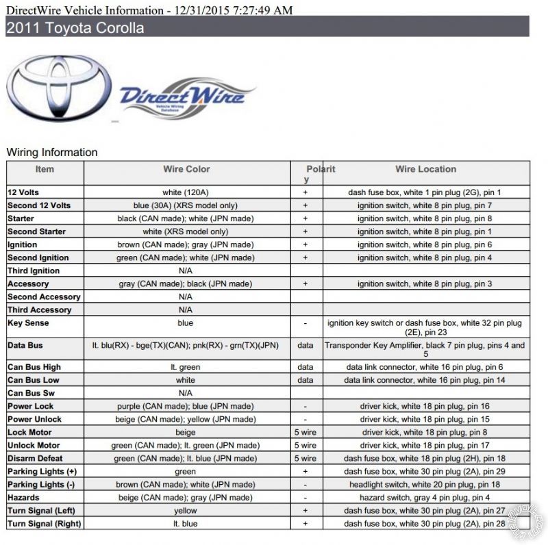
- While I'm at it, the DEI info sheet for the 2011 Corolla can be found below...
2011 Corolla + Viper 5706V + iDatalink ADS-AL-CA -- posted image.
The wiring diagram iDatalink provides seems to be very straightforward and am pretty sure I understand all the connections. In summary:
- All the dashed connections between the Viper unit and the iDatalink bypass are replaced by the D2D connection and are not needed to be made.
- Three IMI and IMO connections must be run through the firewall to the ECU, with IMI being cut/soldered and the IMO being tapped/soldered, according to the diagram.
- CANH and CANL are easily tapped into near the OBD2 connector.
- Ground (-) (ORANGE / black wire) will be run to the engine bay and connected to the hood pin supplied in the Viper kit.
- Ground (-) (blue/red wire) will be grounded using the common ground on the frame near the kick-panel.
- The ignition input will tap into ignition 1 that is shared with the Viper unit.
- MOSTLY, I just want to confirm that the security light connection (blue / YELLOW wire) is run towards the security light behind the center console, and that is the location of the E48/E60 connector.
I have yet to receive the 508D sensor, but if anyone has some insight on how to install it and where it needs to be located in the vehicle, that would be great. I know it just connects into one of the sensor ports on the Viper unit, but does it need to be positioned central in the vehicle for it to work properly?
The Fortin TOY-1 ignition harness was purchased to limit the amount of splicing needed to be done. Again, I have not received it yet in the mail. Im pretty sure the "T" portion of the harness will be useless in terms of connecting to my Viper unit, but I plan on just cutting off the connector and soldering to the correct ignition wires from the Viper unit.
And like many others, my biggest worry is ensuring that I connect the Viper unit correctly.
Main Harness, 6-pin connector:
1) RED - (+)12VDC CONSTANT INPUT --> large white 12V supply under the dash.
2) BLACK - (-) CHASIS GROUND --> common ground on the frame near the kick-panel.
3) BROWN - (+) SIREN OUTPUT --> siren under the hood.
4) WHITE/ BROWN - PARKING LIGHT ISOLATION WIRE --> NC
5) WHITE - PARKING LIGHT OUTPUT --> headlight connector, white 20 pin plug, pin 18
6) ORANGE - (-) 500mA GWA OUTPUT --> NC
Remote Start, 10-pin heavy guage connector
1) NC - No Connection --> NC
2) RED / BLACK - (+) FUSED 12V ACCESSORY/STARTER INPUT -->
3) PINK/BLACK - (+) FLEX RELAY INPUT 87A key side (if required) of FLEX RELAY --> NC??
4) PINK/WHITE - (+) IGNITION 2 / FLEX RELAY OUTPUT -->
5) RED - (+) FUSED 12V IGNITION 1 INPUT --> ignition switch, white 8 pin plug, pin 6
6) GREEN - (+) STARTER INPUT (KEY SIDE OF THE STARTER KILL) -->
7) VIOLET - (+) STARTER OUTPUT (CAR SIDE OF THE STARTER KILL) -->
8) ORANGE - (+) ACCESSORY OUTPUT --> ignition switch, white 8 pin plug, pin 3
9) RED / WHITE - (+) FUSED 12V IGNITION 2 / FLEX RELAY INPUT 87 -->
10) PINK - (+) IGNITION 1 INPUT/OUTPUT -->
So as you can see above, lots of blanks. I have the diagram from iDatalink to confirm the pin locations of each wire at the ignition connector, but dont know the order to connect them to the Viper unit. I understand that there may be some programming to be done in the menus to set them correctly. Any help here would be greatly appreciated.
As for the 24-pin connector, I feel like most do not require any connection to the vehicle. Is that largely correct?
- Pin 1 and 17 reference connections to ignition 2 and ignition 1 respectively, are they required to be connected?
- Pin 2 references rear defogger output. I do indeed want to have the rear defogger running upon startup for sometime, and I know that it operates as a negative latched circuit.
- Pin 4 can trigger the dome lights, is this something that would be useful? I dont know when the Viper unit would want to turn them on.
- Pin 13 connects to the clutch connector, light green cable at pin 1, correct? --> Anyone have a better method than having to shut down the vehicle with Viper's process for manual transmissions?
Anyway, that was a lot haha I hope lots made sense and you can all provide some insight into my install. If anyone is interested, I will probably take pictures throughout and compile a how to for the vehicle. Thanks everyone!
kreg357 
Platinum - Posts: 7,781
Platinum spaceThis member has made a donation to the12volt.com. Click here for more info.spaceThis member has been recognized as an authority in Electrical Theory. Click here for more info.spaceThis member has been recognized as an authority in Mobile Security and Convenience. Click here for more info.spacespace
Joined: January 30, 2009
Location: Pennsylvania, United States
Posted: January 08, 2016 at 11:15 AM / IP Logged Link to Post Post Reply Quote kreg357

Here are the H3 connections ( 2011 Corolla Canadian made ) :

Remote Start, 10-pin heavy gauge connector

1) NC - No Connection --> NC
2) RED / BLACK - (+) FUSED 12V ACC/STARTER   White (120A) +   @ dash fuse box, white 1 pin plug (2G), pin 1
3) PINK/BLACK - (+) FLEX RELAY INPUT 87A     not used
4) PINK/WHITE - (+) IGNITION 2 / FLEX Green  +  ignition switch, white 8 pin plug, pin 4
5) RED - (+) FUSED 12V IGNITION 1 INPUT        White (120A) +   @ dash fuse box, white 1 pin plug (2G), pin 1
6) GREEN - (+) STARTER INPUT (KEY SIDE)      Black  +  ignition switch, white 8 pin plug, pin 8
7) VIOLET - (+) STARTER OUTPUT (CAR SIDE) Black  +  ignition switch, white 8 pin plug, pin 8
8) ORANGE - (+) ACCESSORY OUTPUT   Gray  +  ignition switch, white 8 pin plug, pin 3
9) RED / WHITE - (+) FUSED 12V IGNITION 2 / FLEX       White (120A) +   @ dash fuse box, white 1 pin plug (2G), pin 1
10) PINK - (+) IGNITION 1 INPUT/OUTPUT          Brown  +  ignition switch, white 8 pin plug, pin 6

Soldering is fun!
kreg357 
Platinum - Posts: 7,781
Platinum spaceThis member has made a donation to the12volt.com. Click here for more info.spaceThis member has been recognized as an authority in Electrical Theory. Click here for more info.spaceThis member has been recognized as an authority in Mobile Security and Convenience. Click here for more info.spacespace
Joined: January 30, 2009
Location: Pennsylvania, United States
Posted: January 08, 2016 at 11:46 AM / IP Logged Link to Post Post Reply Quote kreg357

Some more info :

The only thing you are missing is the clutch interlock bypass.  Here is that info :

Clutch Pedal      LT GREEN (+)      @ BLACK 2 PIN CONNECTOR AT CLUTCH PEDAL PIN 1
You should put a DMM on this wire and see if it does go to +12V when the clutch pedal is fully depressed.  If it is a (+)
signal, you will need a relay to properly interface this wire.  Here is the relay wiring :
Relay Pin 85 to Viper H2/17 PINK (-) 200mA IGNITION 1 OUTPUT
Relay Pins 86 and 87 to +12V constant through 10 Amp fuse
Relay Pin 30 to LT GREEN (+)  @ BLACK 2 PIN CONNECTOR AT CLUTCH PEDAL, PIN 1

Another way to do it would be like this :

Relay Pin 85 to Viper H2/17 PINK (-) 200mA IGNITION 1 OUTPUT
Relay Pin 86 to +12V constant through 3 amp fuse
Relay Pin 87 to Pin 2 of BLACK 2 PIN CONNECTOR AT CLUTCH PEDAL
Relay Pin 30 to LT GREEN (+) @ BLACK 2 PIN CONNECTOR AT CLUTCH PEDAL, PIN 1

Pin H2/13 should be connected to the EBrake.  The bypass module supplies this signal and I believe that this will be

handled by the D2D harness automatically.

If your Corolla does not have the factory alarm system and factory hood pin, the bypass module can not obtain this

signal and supply it to the Viper.  In this case you must install the Viper kit supplied hood pin and hardwire it to H2/9.

You will probably not need Dome Light Supervision.  The Corolla does this automatically with an unlock command.

Special provisions must be made if your Corolla has AutoHeadlights unless you never leave the switch in this position.

The Viper must be set to Engine Checking = Tach on a vehicle with a manual transmission.  Perform a Tach Learn after

the bypass module is programmed to the car and prior to attempting a remote start.

Soldering is fun!
spiiiitz 
Member - Posts: 6
Member spacespace
Joined: January 08, 2016
Location: Alberta, Canada
Posted: January 11, 2016 at 5:04 PM / IP Logged Link to Post Post Reply Quote spiiiitz
kreg357:
Thanks for the info, I greatly appreciate it. I don't have either a factory alarm or hood pin, and have already spotted a location in the engine bay to install the one supplied by Viper. I don't have auto headlights, so all gravy there. Some numbered questions I do have for you...
1) For clarity and conversation ease, I want to confirm that H1 = Main Harness; H2 = Auxiliary/Shutdown/Trigger Harness; H3 = Remote Start.
2) With H3/2/5/9 asking for 12V inputs, I'm assuming that I just solder them all together at the white 120A wire. I will be looking for guides here on 12V on how to solder such a combo, but I was planning to just create an opening along the large white wire, twist H3/2/5/9 around it, solder and tape.
- If you had any advice/links, that would be appreciated.
3) What are your thoughts about using the Fortin ignition harness to limit splicing into the stock wiring? Good idea or just a waste of cash? I like the idea of keeping things as plug and play as possible, not because I'm afraid of splicing/soldering, but to retain that ability to pull it out if needed later down the road.
4) To confirm, H1/4/6 are not used and the parking light fuse on the Viper should be set to negative.
5) The bypass module calls for a security light connection using the blue / YELLOW wire. iDatalink states it is located "at security light". Am i really just taking out the dash pieces holding the security light, and the connector will be right there? Not sure if you have experience with a Toyota in that regard.
7) Questions on H2:
- A) With E-brake status being provided over D2D, H2/13 is not needed, correct?
- B) It appears that I can use H2/2 for a rear defogger. To confirm, I just need to locate the wire behind the switch (beige), tap in and program the Viper unit. Menu 3, item 11, option 2. However, I don't see the ability to set the time duration. How long will it stay on?
- C) In summary for H2, I am only connecting up wires to H2/2 (rear defog); H2/9 (hood pin); H2/17 (clutch bypass relay). Correct?
8) The clutch interlock bypass relay you described, is this a requirement intended to satisfy the car's computer? I'm assuming even with the iDatalink bypass module, it will still refuse to start without this circuit being grounded.
9) Do you have any recommendations for manual transmission vehicles, and not having to put the car in reservation mode every time when turning the engine off? I am fully aware as to why they are needed, but is there another method that can be used that is easier?
- I've seen guys install neutral safety switches below there shifter using eBay parts, but I am a little weary of that solution.
MANY THANKS for your help kreg, and if anyone has some input, I'd also love to hear from you.
kreg357 
Platinum - Posts: 7,781
Platinum spaceThis member has made a donation to the12volt.com. Click here for more info.spaceThis member has been recognized as an authority in Electrical Theory. Click here for more info.spaceThis member has been recognized as an authority in Mobile Security and Convenience. Click here for more info.spacespace
Joined: January 30, 2009
Location: Pennsylvania, United States
Posted: January 11, 2016 at 7:30 PM / IP Logged Link to Post Post Reply Quote kreg357

1.  Yes.  That seems to be the most popular harness ID convention.

2. Power wires.  There are actually 4 fused +12V inputs to the Viper.  I think I would run all 4 to that thick White wire.

    Then I would combine them into 2 pairs with a 3" section at the end.  This 3" section would then be soldered to the
     thick White wire.  That would allow only 2 solder joints and a very short section of single 12 gauge wire before the
     split.  It will handle the load and keep things neat and simple.

3.  I typically don't use the T Harness's.  They don't save too much time for the extra cost.  A well laid out install with 

     quality solder connections will last the cars life time.  Removal is simple, cut and tape.

4.  Yes.  Not needed for your application.

5. The iDatalink guides are usually fairly well written and accurate.  I have not done a 2011 Corolla with the ADS AL CA

    but I believe the connector is there at the Security Light below the A/C controls in the center stack next to the clock. 
    Here is a link to the owners manual info : 
    http://www.toyota.com/t3Portal/document/om/OM12D65U/xhtml/OM12D65U_0010.html?locale=en

6. missing

7.  A.  Yes, hopefully.  You will find out quickly enough when you try to go into reservation mode.

     B.  The Rear Defrost output is a (-) 200mA signal that comes on 10 seconds after a R/S if the interior cabin temp is
below 55 degrees and stays on for 10 minutes ( latched ) or until prior R/S shutdown or on key take-over. 
     C.  Yes.  If the D2D connection supplies all the signals it's supposed to, then only those 3 wires are needed.

8.  Correct.  The bypass module can not and will not over-ride or bypass a safety interlock as important as that.  The

     clutch interlock is part of the Corolla's design.   The starter motor will not crank if the clutch pedal is not fully depressed.

9.  On some vehicles there is an actual "manual transmission neutral signal" produced by the ECM.  Subaru's are known

     to have this signal.  I have not heard of a similar signal on Toyota's.  While I only go with a clutch interlock bypass
     and a manual transmission safe R/S system on the few MT vehicles I do, I would accept a "neutral" signal from the
     vehicles' ECM but never try to create this signal myself ( with parts / micro switches from EBay ).  It's not just the
     garage door you are protecting but the 4 year old child playing behind it...

Soldering is fun!
spiiiitz 
Member - Posts: 6
Member spacespace
Joined: January 08, 2016
Location: Alberta, Canada
Posted: January 12, 2016 at 1:35 PM / IP Logged Link to Post Post Reply Quote spiiiitz
Once again, thank you for taking the time to provide such a detailed response. I wont be able to conduct the install until later next week, but will definitely follow-up here for (hopefully) a success story!
I do have just a couple other questions:
1) The Viper unit will signal the rear defogger if the temperature is below 55 degrees. Is there a way to set it so that it comes on when the temperature is a lot lower? 55 degrees is actually pretty warm, warm enough where I would never need the defogger to be turned on. I'm thinking something like 15-20 degrees would be an ideal threshold for it to be activated, if possible.
2) To set up the relay that you described, is the relay included with the Viper unit? I don't have the Viper R/S yet, as it is still being shipped my way, so I can't look myself.
3) In regards to the relay again, I have read that others with manual transmissions have lost their cruise control function. I'm assuming in their case, they have just permanently grounded their clutch interlock? Or am I too at risk of losing cruise as well?
If anyone browsing the forum has ideas on running the unit safely and reliably in automatic mode on a manual transmission vehicle, please let me know. I understand the rationale completely behind reservation mode, but it looks to be such a PITA to do every time. However, I can justify compromising safety for convenience. Like kreg said, it could very well be someone instead of something that gets cranked.
Thanks again kreg, you have really come through and cleared up a lot for me! As you can tell, I am really getting down to every detail possible before I attempt this project haha I will probably have 10 other questions leading up to the actual install weekend, but for now, that's all I got :)
kreg357 
Platinum - Posts: 7,781
Platinum spaceThis member has made a donation to the12volt.com. Click here for more info.spaceThis member has been recognized as an authority in Electrical Theory. Click here for more info.spaceThis member has been recognized as an authority in Mobile Security and Convenience. Click here for more info.spacespace
Joined: January 30, 2009
Location: Pennsylvania, United States
Posted: January 12, 2016 at 7:38 PM / IP Logged Link to Post Post Reply Quote kreg357

1.  Not a big Viper person, but I don't think there is a way to change the Defrost temperature.

2. The relay is not included with the Viper kit.  A standard Bosch Automotive 30/40 Amp SPDT relay is what you need.

    Get one with the 5 wire harness.  Typical price is under $5.  Search EBay, there are many listings.  Get a 2 pack, just
    in case.  Something like this :   
    http://www./itm/2X-The-Install-Bay-RL3040-12V-30-40-AMP-Bosche-Style-Relay-w-Socket-2-Pack-/400973931879?hash=item5d5be8a567:g:ErsAAOSw585WUZwu

3.  There are typically two switches on the clutch pedal.  One for starter interlock that engages at the bottom of pedal

     travel and another for the cruise control disengagement that triggers near the top of pedal travel.  Done correctly
     with the relay as shown, it will not cause any problems with the vehicles normal operation.  The relay only comes
     on during a remote start.  At all other times it is passive and does not interfere with anything.

Soldering is fun!
spiiiitz 
Member - Posts: 6
Member spacespace
Joined: January 08, 2016
Location: Alberta, Canada
Posted: January 23, 2016 at 6:55 PM / IP Logged Link to Post Post Reply Quote spiiiitz
Hi kreg and anyone else who may want to do the same install in the future!
So in short, shes been conquered and everything works as intended! It really isn't all that hard to do for an average joe, as long as you have some experience working with cars and have the patience/time to do it. Some notes that could help others:
1. As suggested everywhere else on the forum, bench prep everything possible. I'm a pretty young guy (23) and even though I finished the install two days ago, my neck and back are still sore. I even took the drivers seat out to give me more room! So make sure you do everything to limit the amount of time under the dash.
2. Everything that was expected to be transferred over D2D came through, but you still need to connect up the neutral safety ground (H2/13).
3. ZIP TIES --> I used probably about 100, give er take.
4. My security light wire was found behind the dash panel with the light, but the connector was totally different. After much research, I was only left with the impression that such wire was yellow. After confirming with a DMM, it was indeed the yellow one (cant remember position, but was the only yellow one there).
5. Rear defog was hooked directly up to the beige wire behind the climate controls. No relay or diode. I feel that I might still need a diode (some say yes, some say no), but it works the way as is.
6. I also used a small spool of wire to extend wires to the engine bay/center console. I bought 16 guage, but felt it was overkill and almost too hard to use when splicing into the super small OEM wires. Use 18-20 gauge would be my recommendation.
7. A location to mount the siren was difficult to find, but ended up placing it just behind the passenger headlight.
8. SOLDER everything, followed by electrical tape and zip ties! Seems like a no brainer, but just do it.
9. Relay worked great as described by kreg...
Relay Pin 85 to Viper H2/17 PINK (-) 200mA IGNITION 1 OUTPUT
Relay Pin 86 to +12V constant through 3 amp fuse
Relay Pin 87 to Pin 2 of BLACK 2 PIN CONNECTOR AT CLUTCH PEDAL
Relay Pin 30 to LT GREEN (+) @ BLACK 2 PIN CONNECTOR AT CLUTCH PEDAL, PIN 1
10. Ignition T-harness was pretty bulky and added to the mass of wires under the dash. Dont get me wrong, it was easy to just plug and play, but because the ignition wires are easily accessed, it really doesn't reduce install time by much.
11. I installed during the week on two nights, but next time I would just set aside a Saturday instead!
12. The IMO/IMI wires in the engine bay were not that bad to get to. I found a nice photo of the wires I was looking for on a 2011 RAV4 here.
https://www.the12volt.com/installbay/forum_posts.asp?tid=133996
13. The idatalink bypass needs to be programmed first. Mine was flashed by an ebay seller with the DBI flavor of the firmware for D2D. When first powered up, it will flash with one light consistently. It means its in D2D mode. Click the button once, and it will flash two times conistently, meaning its in W2W mode. I locked in D2D by holding the button when it flashed once. Trying to program the module with the key took about 5 turns of the ignition back and forth, but once done, the red light will change to a green one to signify its all programmed.
14. The viper module was easy to program, just figure out the options you want in the manual and sit there for 10 mins to change to the options you want.
15. Manual mode so far hasnt been so bad. I just have to remember to not hit the brake a second time with my foot accidentally on my way out/getting things out of the vehicle.
LASTLY, to anyone tackling their first install like me, spend lots of time understanding each wire and their purpose. If you dont, you will fail. They are each pretty self explanatory, but take that time to read, read and reread the diagrams and forums. I spent almost two weeks on and off taking a look at stuff while I waited for things to arrive in the mail.
Sorry I didnt take pictures to do a write-up, it has been close to -20C here at night in Canada. I dont have a heated garage and makes the install hard enough haha
Thanks again kreg and the12volt for all the valuable information provided to us rookies. You saved me almost 400CAD by doing it myself and greatly appreciate it!
mscguy 
Copper - Posts: 212
Copper spacespace
Joined: November 28, 2015
Location: British Columbia, Canada
Posted: January 23, 2016 at 8:15 PM / IP Logged Link to Post Post Reply Quote mscguy
Glad to hear you finished. I wanted to mention about your defogger. It comes on automatically below 55F. Around 12 Celsius or below. You can do it manually by pressing F key 4 times than the start button. I assume you read the manual by now, but just in case, that's how.
spiiiitz 
Member - Posts: 6
Member spacespace
Joined: January 08, 2016
Location: Alberta, Canada
Posted: January 23, 2016 at 9:54 PM / IP Logged Link to Post Post Reply Quote spiiiitz
mscguy thanks for the info! I didnt know that i can manually trigger it by pressing the F key 4 times+start. Would this be used in cases where the temperature is greater than 12C? Or maybe when the remote start is running for longer than 10 minutes and I want to manually trigger the defroster for longer?
Also, not sure if you or anyone else have suggestions for utilizing the additional AUX outputs. I know the possibilities are endless, but I am trying to nail down some sweet/cool/neat/useful ideas for them. I know I don't want to add a module to put windows up/down, as I think I will have very little use for it.
Bu so far I was thinking of using an aux channel to trigger the A/C system in the car. I cant find any information on the forum/internet regarding which wire corresponds to the A/C button (and if I just have to tap into it, similar to the defroster relay circuit), so if anyone had some guidance on that one, I would appreciate it.
Any other insights on which circuits to tap into with the AUX wires? Mucho Gracias!
Page of 2

  Printable version Printable version Post ReplyPost New Topic
You cannot post new topics in this forum
You cannot reply to topics in this forum
You cannot delete your posts in this forum
You cannot edit your posts in this forum
You cannot create polls in this forum
You cannot vote in polls in this forum

  •  
Search the12volt.com
Follow the12volt.com Follow the12volt.com on Facebook
Thursday, March 28, 2024 • Copyright © 1999-2024 the12volt.com, All Rights Reserved Privacy Policy & Use of Cookies
Disclaimer: *All information on this site ( the12volt.com ) is provided "as is" without any warranty of any kind, either expressed or implied, including but not limited to fitness for a particular use. Any user assumes the entire risk as to the accuracy and use of this information. Please verify all wire colors and diagrams before applying any information.

Secured by Sectigo
the12volt.com spacer
Support the12volt.com
Top
the12volt.com spacer