the12volt.com spacer
icon

'13 Tacoma CM7000AS with Blade Al


Post ReplyPost New Topic
< Prev Topic Next Topic >
jdmegcoupe 
Copper - Posts: 80
Copper spaceThis member has made a donation to the12volt.com. Click here for more info.spacespace
Joined: October 15, 2003
Location: Massachusetts, United States
Posted: January 20, 2016 at 10:55 AM / IP Logged Link to Post Post Reply Quote jdmegcoupe
Hello all,
I hope everyone is doing well. I am gonna give this a shot. Would anyone be able to help me with wiring a CM7000AS with a Blade AL into my 2013 Tacoma. Like a wire for wire write up. Please. I would like to get this done ASAP before the snow storm hits this weekend in Massachusetts.
Thank you.
I hope to hear back.
mscguy 
Copper - Posts: 212
Copper spacespace
Joined: November 28, 2015
Location: British Columbia, Canada
Posted: January 20, 2016 at 12:01 PM / IP Logged Link to Post Post Reply Quote mscguy
http://www.readyremote.com/main.asp?action=select&yr=26754&product=Remote%20Start&make=Toyota&model=Tacoma
Did your unit come with an install manual? It may even be written on the back of the 7000.
http://techfeed.compustar.com/ft_controllers/manuals/CM7000_Full_Install_3.00_EN.pdf
Your vehicle doesn't look very difficult. You'll need a relay for the 2nd starter wire.
jdmegcoupe 
Copper - Posts: 80
Copper spaceThis member has made a donation to the12volt.com. Click here for more info.spacespace
Joined: October 15, 2003
Location: Massachusetts, United States
Posted: January 21, 2016 at 6:47 AM / IP Logged Link to Post Post Reply Quote jdmegcoupe
mscguy wrote:
http://www.readyremote.com/main.asp?action=select&yr=26754&product=Remote%20Start&make=Toyota&model=Tacoma
Did your unit come with an install manual? It may even be written on the back of the 7000.
http://techfeed.compustar.com/ft_controllers/manuals/CM7000_Full_Install_3.00_EN.pdf
Your vehicle doesn't look very difficult. You'll need a relay for the 2nd starter wire.
Thank you SiR! I got the cn1 figured out for the most part except on how to wire the FT-ELock. And the wiring for the cn5 has me a bit confused.
mscguy 
Copper - Posts: 212
Copper spacespace
Joined: November 28, 2015
Location: British Columbia, Canada
Posted: January 21, 2016 at 7:14 AM / IP Logged Link to Post Post Reply Quote mscguy
Did your 7000 come with an install guide? your ft-elock instructions are in there.
jdmegcoupe 
Copper - Posts: 80
Copper spaceThis member has made a donation to the12volt.com. Click here for more info.spacespace
Joined: October 15, 2003
Location: Massachusetts, United States
Posted: January 21, 2016 at 7:17 AM / IP Logged Link to Post Post Reply Quote jdmegcoupe
I will have to check when I get home front work today! If I make template of what wires go to what wires can I pm it to you and you verify they are right before I begin?
mscguy 
Copper - Posts: 212
Copper spacespace
Joined: November 28, 2015
Location: British Columbia, Canada
Posted: January 21, 2016 at 7:24 AM / IP Logged Link to Post Post Reply Quote mscguy
Just post on here so others can look too. Imo, it's always good to have more sets of eyes on something. I'm just a helpful diy'er so someone else may see something that I don't.
jdmegcoupe 
Copper - Posts: 80
Copper spaceThis member has made a donation to the12volt.com. Click here for more info.spacespace
Joined: October 15, 2003
Location: Massachusetts, United States
Posted: January 23, 2016 at 8:02 PM / IP Logged Link to Post Post Reply Quote jdmegcoupe
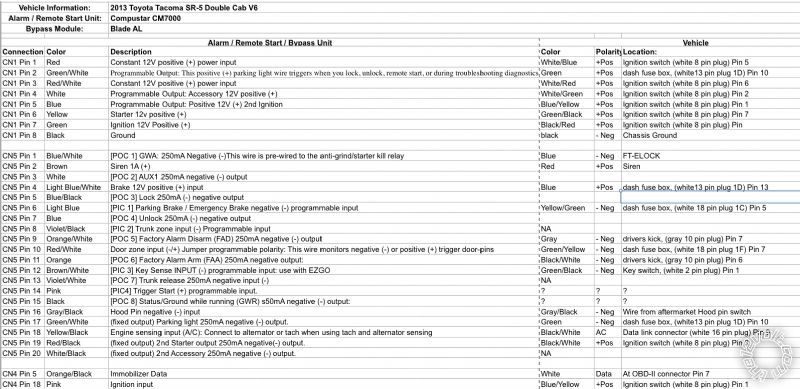
Okay Can anyone tell me if this is right? If the wiring is correct?Thanks
'13 Tacoma CM7000AS with Blade Al -- posted image.
mscguy 
Copper - Posts: 212
Copper spacespace
Joined: November 28, 2015
Location: British Columbia, Canada
Posted: January 23, 2016 at 10:52 PM / IP Logged Link to Post Post Reply Quote mscguy
CN5 Pin 6 - YELLOW /GREEN.   Ready remote says GREEN/ YELLOW. Check anyway
CN5 pin 9 - GREEN/ black   Double (-) driver kick, gray 10 pin plug, pin 8
CN5 Pin 11 - Purple driver kick, gray 10 pin plug, pin 4
CN5 Pin 12 - Keysense. Idatalink guide says "Warning Don't connect keysense" to the starter. Not sure why, just going off the manual.
CN5 Pin 19. DON'T DO THIS the way you wrote. Your second starter is a positive connection. Connecting this to the small -250ma wire is a sure way to cook your module.
You need to use a relay to power this.
86 - +12V
85 - -250ma starter out CN5 Pin 19
87 - +12V fused.
30 - Car starter 2 wire. (BLACK/ white) ign harness
Other than these, it looks ok.
I'm getting my wires purely off the ready remote site. I'm not sure why some of yours are different. Please make sure to test all wires first.
jdmegcoupe 
Copper - Posts: 80
Copper spaceThis member has made a donation to the12volt.com. Click here for more info.spacespace
Joined: October 15, 2003
Location: Massachusetts, United States
Posted: January 24, 2016 at 1:42 PM / IP Logged Link to Post Post Reply Quote jdmegcoupe
Okay I messed up writng the wires because I was tired last night. Fixed Let me know if this is all right now. Thank you
'13 Tacoma CM7000AS with Blade Al -- posted image.
mscguy 
Copper - Posts: 212
Copper spacespace
Joined: November 28, 2015
Location: British Columbia, Canada
Posted: January 24, 2016 at 6:25 PM / IP Logged Link to Post Post Reply Quote mscguy
In that relay picture, you wrote CN1/3 to 87A, then 87A to starter side. If I'm reading your spreadsheet right, that will just send +12V constantly to your starter.   Do you mean CN1/6 to 87A?
Cn5/9 still looks wrong.     GREEN/ black (driver door key unlock)      double -      driver kick, gray 10 pin plug, pin 8
Other than that, I think it looks ok.
Page of 2

  Printable version Printable version Post ReplyPost New Topic
You cannot post new topics in this forum
You cannot reply to topics in this forum
You cannot delete your posts in this forum
You cannot edit your posts in this forum
You cannot create polls in this forum
You cannot vote in polls in this forum

  •  
Search the12volt.com
Follow the12volt.com Follow the12volt.com on Facebook
Thursday, April 18, 2024 • Copyright © 1999-2024 the12volt.com, All Rights Reserved Privacy Policy & Use of Cookies
Disclaimer: *All information on this site ( the12volt.com ) is provided "as is" without any warranty of any kind, either expressed or implied, including but not limited to fitness for a particular use. Any user assumes the entire risk as to the accuracy and use of this information. Please verify all wire colors and diagrams before applying any information.

Secured by Sectigo
the12volt.com spacer
Support the12volt.com
Top
the12volt.com spacer