


 the12volt
 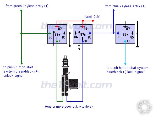 You will need three SPDT relays. Disconnect the actuators from the keyless entry module and connect the wires from the actuators, from the keyless entry module, and to the push button start system as shown above. The keyless entry system will no longer be connected directly to each actuator.
This will provide the positive unlock and negative lock signals to the push button start system from the keyless entry module.
If you add a door lock switch in the future, you will need two additional relays to isolate the door lock switch from the keyless entry module and to prevent it from interfering with the push button start system. When you're ready for that, let know and I'll draw another diagram.
You will need three SPDT relays. Disconnect the actuators from the keyless entry module and connect the wires from the actuators, from the keyless entry module, and to the push button start system as shown above. The keyless entry system will no longer be connected directly to each actuator.
This will provide the positive unlock and negative lock signals to the push button start system from the keyless entry module.
If you add a door lock switch in the future, you will need two additional relays to isolate the door lock switch from the keyless entry module and to prevent it from interfering with the push button start system. When you're ready for that, let know and I'll draw another diagram. Printable version


| You cannot post new topics in this forum You cannot reply to topics in this forum You cannot delete your posts in this forum You cannot edit your posts in this forum You cannot create polls in this forum You cannot vote in polls in this forum |

| Search the12volt.com |
Follow the12volt.com 
Thursday, April 2, 2026 • Copyright © 1999-2026 the12volt.com, All Rights Reserved • Privacy Policy & Use of Cookies

Thursday, April 2, 2026 • Copyright © 1999-2026 the12volt.com, All Rights Reserved • Privacy Policy & Use of Cookies
Disclaimer:
*All information on this site ( the12volt.com ) is provided "as is" without any warranty of any kind, either expressed or implied, including but not limited to fitness for a particular use. Any user assumes the entire risk as to the accuracy and use of this information. Please
verify all wire colors and diagrams before applying any information.
