the12volt.com spacer
icon

Chinese Alarm Lock/unlock not triggering?


Post ReplyPost New Topic
< Prev Topic Next Topic >
nidish 
Member - Posts: 29
Member spacespace
Joined: August 01, 2015
Location: Neutral Zone
Posted: October 28, 2016 at 1:53 AM / IP Logged Link to Post Post Reply Quote nidish
Hey guys, I have a 2004 Mitsubishi Lancer. My car has central lock but no keyless entry.
I purchased a chinese alarm off ebay.
I found the lock/unlock wire by using a DMM. I set it to 12v dc. I put black to ground and red to test wires. On one wire, when I unlock the car, it shows 12V and then goes to zero and when I lock, on the other wire it shows 12v and then goes to zero. My car has a negative door lock system.
I hook the Green wire from the chinese alarm to lock wire on the car harness and orange wire to unlock.
Here is a pic of the chinese alarm.
Chinese Alarm Lock/unlock not triggering? -- posted image.
Everything works except for the door lock and unlock with remote. What am I doing wrong?
I won't be wiring starter kill relay and not use trunk release.
Please help me out.
nidish 
Member - Posts: 29
Member spacespace
Joined: August 01, 2015
Location: Neutral Zone
Posted: October 28, 2016 at 2:55 AM / IP Logged Link to Post Post Reply Quote nidish
One thing i forgot to mention: if I unlock the car with the key from the passenger side, all door are unlocked except for the driver side. However, if I unlock the car with the key from the driver side, then all four doors are unlocked. I'm talking about unlocking from outside the car with the key, not from inside.
What does this mean? Is this why wiring lock/unlock wires directly from the alarm to central lock of car not working?
KPierson 
Platinum - Posts: 3,527
Platinum spaceThis member consistently provides reliable informationspace
Joined: April 14, 2005
Location: Ohio, United States
Posted: October 28, 2016 at 9:09 PM / IP Logged Link to Post Post Reply Quote KPierson
It sounds to me like you found the actual door lock actuator wires. These are high current wires that connect to the solenoids that actually make the doors physically lock and unlock. From the limited amount you show from the manual your alarm outputs a low current (-) signal.
To test for the low current door lock control wires in a negative trigger locking system you should put your red lead on a 12vdc source and use the black lead to probe the wires. When you find the correct wires the meter will go to 12vdc.
For a 2004 Lancer:
POWER LOCK      PURPLE or YELLOW (TYPE B)      IN DRIVERS KICK PANEL, HARNESS TO REAR OF VEHICLE      
POWER UNLOCK      LIGHT GREEN/ RED or LIGHT GREEN (TYPE B)      IN DRIVERS KICK PANEL, HARNESS TO REAR OF VEHICLE
If you have, in fact, found the actuator wires you could make them work, but you would need to add relays - something that is not required at all when you do it the correct way.
Kevin Pierson
nidish 
Member - Posts: 29
Member spacespace
Joined: August 01, 2015
Location: Neutral Zone
Posted: October 28, 2016 at 9:52 PM / IP Logged Link to Post Post Reply Quote nidish
Thank you a lot for your help mate. :) I tested the wires with a multi meter with the black lead to ground and red to test the wire. On the multimeter, it shows 0v but when I unlock or lock the car, depending on the two wires I found, when I press lock/unlock from dr5iver side door, the voltage goes to 12v quickly and back to zero. Is that the wrong way of doing it?
Here's the PDF version of the alarm I'm installing. You can DL it from dropbox:
https://dl.dropboxusercontent.com/u/17323329/ZJ213600ENmanual.pdf
howie ll 
Pot Metal - Posts: 16,466
Pot Metal spacespace
Joined: January 09, 2007
Location: United Kingdom
Posted: October 29, 2016 at 9:25 AM / IP Logged Link to Post Post Reply Quote howie ll
If you did go to the motor wires you've probably fried the alarm's lock circuit by now.
There's actually a much easier way to test for the lock triogger wires.
Use a Snap-On or similar incandescant bulb test light, clip to ground then probe end to suspect wire, you'll probably need to throw the catch at the rear of the door and remove key from ignition switch.
nidish 
Member - Posts: 29
Member spacespace
Joined: August 01, 2015
Location: Neutral Zone
Posted: November 02, 2016 at 10:30 AM / IP Logged Link to Post Post Reply Quote nidish
howie, is there any way to test the alarm main unit itself to find if I've fried the lock circuit?
howie ll 
Pot Metal - Posts: 16,466
Pot Metal spacespace
Joined: January 09, 2007
Location: United Kingdom
Posted: November 02, 2016 at 2:14 PM / IP Logged Link to Post Post Reply Quote howie ll
Test light or DMM set red probe or test light clip to a constant 12V+ , other side to suspect wire on alarm lock and unlock you should either get illumination or 12V+ on your DMM if working. Obviously do one at a time.
nidish 
Member - Posts: 29
Member spacespace
Joined: August 01, 2015
Location: Neutral Zone
Posted: November 06, 2016 at 2:10 AM / IP Logged Link to Post Post Reply Quote nidish
Ok guys, based on what KPierson told me, I'm getting four wires. Two of them when I unlock or lock respectively, from 12volt goes to almost 0 volts(sometime 5 volts) and then goes back to 12 volts.
The other two wires, when I lock or unlock go from 12volt to zero and remains at zero until I lock or unlock then goes back to 12 volts.
Which wires should I connect to my chinese alarm system? Also do I need to connect both unlock/lock wires to the alarm or can I connect only one, i.e either lock or unlock to test with the remote if it's working? Can the doors be left open while testing? Thanks
KPierson 
Platinum - Posts: 3,527
Platinum spaceThis member consistently provides reliable informationspace
Joined: April 14, 2005
Location: Ohio, United States
Posted: November 07, 2016 at 11:43 PM / IP Logged Link to Post Post Reply Quote KPierson
You would want to connect to the wires that pulse. You should be able to simulate this by applying a ground, through a ~100 ohm resistor, to the wire in question. If they are the correct wires the doors should lock and unlock when grounded through the resistor. The resistor is key because, if they are the wrong wires, it will restrict the amount of current and drastically lower the chances of damaging anything.
Kevin Pierson
nidish 
Member - Posts: 29
Member spacespace
Joined: August 01, 2015
Location: Neutral Zone
Posted: November 07, 2016 at 11:52 PM / IP Logged Link to Post Post Reply Quote nidish
Also, after trying to figure out why it wasnt working, I notice that on my driver door, right next to the power window control buttons, there is no lock/unlock switch. So when testing I press the physical lock/unlock button right next to the handle that opens the door. Is this why I'm having all this issue?
So I continue to read on the 12volt forum and it says:
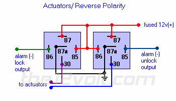
If there are no external door lock switches, you will most likely have a vacuum type system or an *aftermarket door lock system with relays, or have an added actuator that needs relays.
So I figured out I would use the actuator diagram b/c my car being Mitsubishi which is japanese is very unlikely to have vaccumm type door lock.
Chinese Alarm Lock/unlock not triggering? -- posted image.
I wire the lock/unjlock wire of the alarm to two relays like in the above picture and I connect only one function first, the unlock just to test, but when i press the remote, it doesn't unlock, instead it blows the fuse of the alarm system.
Page of 2

  Printable version Printable version Post ReplyPost New Topic
You cannot post new topics in this forum
You cannot reply to topics in this forum
You cannot delete your posts in this forum
You cannot edit your posts in this forum
You cannot create polls in this forum
You cannot vote in polls in this forum

  •  
Search the12volt.com
Follow the12volt.com Follow the12volt.com on Facebook
Thursday, April 25, 2024 • Copyright © 1999-2024 the12volt.com, All Rights Reserved Privacy Policy & Use of Cookies
Disclaimer: *All information on this site ( the12volt.com ) is provided "as is" without any warranty of any kind, either expressed or implied, including but not limited to fitness for a particular use. Any user assumes the entire risk as to the accuracy and use of this information. Please verify all wire colors and diagrams before applying any information.

Secured by Sectigo
the12volt.com spacer
Support the12volt.com
Top
the12volt.com spacer