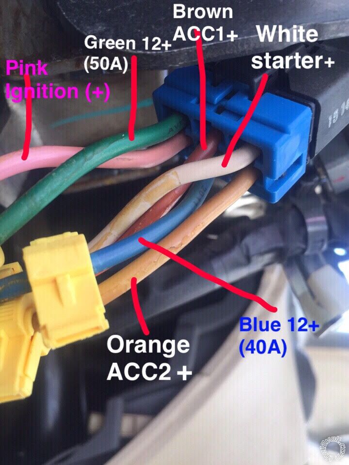
Well, going by your photo and using the colors marked, here are the updated connections
for your car ( which, BTW, does not match a U.S. market 2012 Accent ).
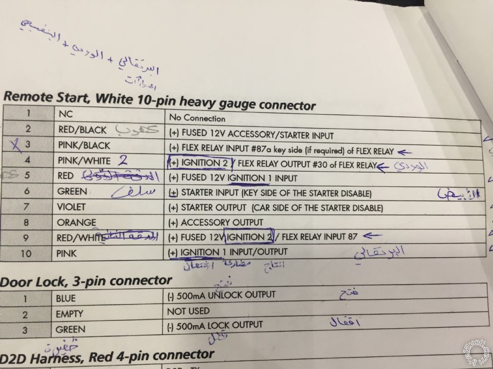
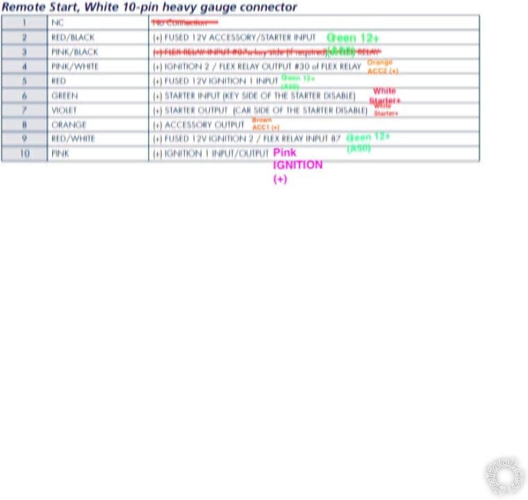
Remote Start, 10-pin heavy gauge connector
1 NC No Connection
2 RED/BLACK (+) FUSED 12V ACC/STARTER INPUT......Blue (40A) IGNITION SWITCH BLACK 6 PIN CONN, PIN 5
3 PINK/BLACK (+) FLEX RELAY INPUT 87A...................not used
4 PINK/WHITE (+) IGNITION 2 ***set to ACC2...............Orange IGNITION SWITCH BLACK 6 PIN CONN, PIN 6
5 RED (+) FUSED 12V IGNITION 1 INPUT....................GREEN (50A) IGNITION SWITCH BLACK 6 PIN CONN, PIN 1
6 GREEN (+) STARTER INPUT (KEY SIDE)..................WHITE IGNITION SWITCH BLACK 6 PIN CONN, PIN 3
7 VIOLET (+) STARTER OUTPUT (CAR SIDE)..............WHITE IGNITION SWITCH BLACK 6 PIN CONN, PIN 3
8 ORANGE (+) ACCESSORY OUTPUT..........................Brown IGNITION SWITCH BLACK 6 PIN CONN, PIN 2
9 RED/WHITE (+) FUSED 12V IGNITION 2..................GREEN (50A) IGNITION SWITCH BLACK 6 PIN CONN, PIN 1
10 PINK (+) IGNITION 1 INPUT/OUTPUT......................PINK IGNITION SWITCH BLACK 6 PIN CONN, PIN 4
Not that it matters for a simple R/S test, but the Pink/White Flex ignition output wire should be changed to
ACC2 ( Menu 3, Feature 8, Option 2 ).
Additionally, I would connect the Viper 15 Amp Red wire in the 6 Pin connector to the vehicles +12V Blue wire
at Pin 5 to split the load between available sources ( Blue and Green wires ).
Other issues :
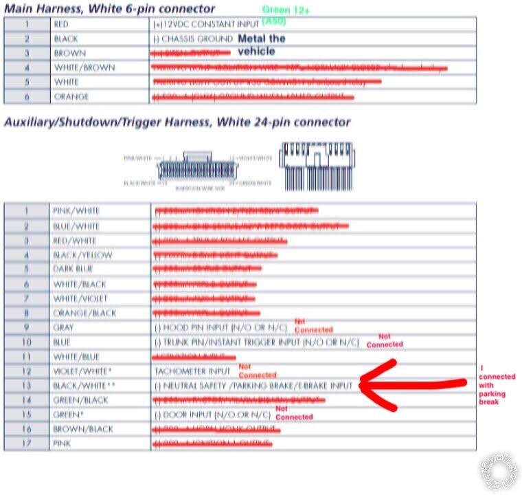
1. For the Viper to run in Manual Transmission Mode, the Tach wire must be connected and a successful Tach Learn preformed.
2. For the Viper to run in Manual Transmission Mode, the Door Pins and Trunk Pin must be connected properly. This is to allow
entry into Reservation Mode ( and for safety ).
3. The Hood Pin is an important safety feature and should installed and connected.
4. As a manual transmission vehicle, you must leave the Viper Menu 3, Feature 1 at its' default Option 1 setting.
5. While not shown, I'm assuming that the Brown Brake (+) wire at Pin 20 is connected.
After you make these corrections, you should be able to successfully enter Reservation Mode and then initiate a remote start.
Of course, there is one more item that needs to be addressed. Do a Remote Start Diagnostics and determine the Error Code.
Post that code and we can provide more info.
Soldering is fun!


 Printable version


