the12volt.com spacer
icon

Viper 211HV and Bulldog RS82B in 01 F-150 SuperCrew


Post ReplyPost New Topic
< Prev Topic Next Topic >
kreg357 
Platinum - Posts: 7,783
Platinum spaceThis member has made a donation to the12volt.com. Click here for more info.spaceThis member has been recognized as an authority in Electrical Theory. Click here for more info.spaceThis member has been recognized as an authority in Mobile Security and Convenience. Click here for more info.spacespace
Joined: January 30, 2009
Location: Pennsylvania, United States
Posted: August 04, 2018 at 6:32 AM / IP Logged Link to Post Post Reply Quote kreg357
Not exactly.
With that unit the wires with Green as the primary color are Lock and Blue as primary are Unlock.
As for Relay pin correlation :
xxx/White = Pin 30
xxx/Red = Pin 87a
xxx/Yellow = Pin 87
So for your Type C application :
xxx/White goes to motor side
xxx/Red goes to switch side
xxx/Yellow goes to +12V constant ( add 15 Amp fuse for circuit protection )
The Parking Light output is only (+) which is OK for your Ford truck. You only need to connect one,
either L or R.
If you really wanted to get fancy, you could use the relays unlock wires for the Drivers door and the (-)Trunk
output to trigger the Second Unlock relay to do all the doors by adding that wire to Pin 85.
Soldering is fun!
rlwolfgram 
Member - Posts: 10
Member spacespace
Joined: November 07, 2013
Posted: August 04, 2018 at 10:19 AM / IP Logged Link to Post Post Reply Quote rlwolfgram
Thank you so much!
Last question....
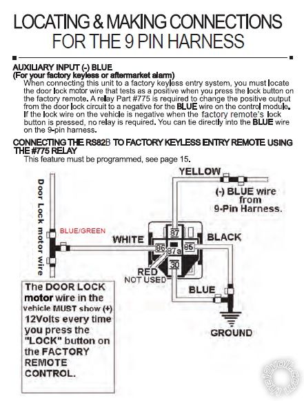
I am also installing an RS82B in my wife's 09 Ford Flex, which does have factory keyless entry. I will be using the factory keyless option on the RS82B where you press the lock button three times to remote start the vehicle. The website says the Flex is a type B lock system. Can I connect the door lock relay (white #86 in picture) directly to the wire directly to the Flex's blue/green lock wire? I am struggling finding a type B lock diagram...
Viper 211HV and Bulldog RS82B in 01 F-150 SuperCrew - Page 2 -- posted image.
kreg357 
Platinum - Posts: 7,783
Platinum spaceThis member has made a donation to the12volt.com. Click here for more info.spaceThis member has been recognized as an authority in Electrical Theory. Click here for more info.spaceThis member has been recognized as an authority in Mobile Security and Convenience. Click here for more info.spacespace
Joined: January 30, 2009
Location: Pennsylvania, United States
Posted: August 04, 2018 at 11:01 AM / IP Logged Link to Post Post Reply Quote kreg357
On the Ford Flex, even though it has Type B locks, you can't use the listed (-) Lock wire as a trigger
input for the RS82B. Even with a relay ( and wired correctly ) it won't work. In this case you must use
a relay to convert the drivers door lock motor wire from a (+) to a (-) and that relay output
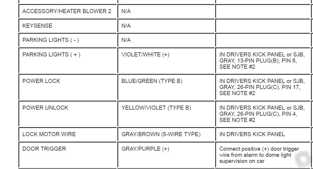
goes to the RS82B as the R/S trigger input. Here is that wires' info from Bulldog Security :
LOCK MOTOR WIRE   GRAY/BROWN (5-WIRE TYPE)   IN DRIVERS KICK PANEL
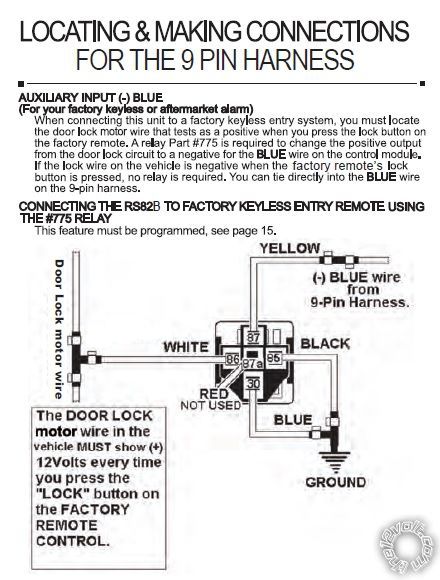
The Bulldog relay diagram above is correct with the Lock Motor wire. Just beware that pressing the
door lock button on the inner door three times in a row will start the vehicle.
For the transponder bypass you can use a programmed Valet key rather than one of the original Factory
keys. You can get them off eBay for about $10, get them cut at a local hardware store for $2 and
easily program them yourself. I would get a couple and get them cut and programmed. Use one for the
RS82B bypass and keep a spare in the house. Having a spare key is always a good idea.   Viper 211HV and Bulldog RS82B in 01 F-150 SuperCrew - Page 2 -- posted image.
Soldering is fun!
rlwolfgram 
Member - Posts: 10
Member spacespace
Joined: November 07, 2013
Posted: August 04, 2018 at 11:18 AM / IP Logged Link to Post Post Reply Quote rlwolfgram
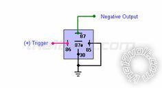
So this, where the trigger is the door lock wire gray/brown, & negative output is directly to the RS82B blue wire (no relay needed?)
Viper 211HV and Bulldog RS82B in 01 F-150 SuperCrew - Page 2 -- posted image.
kreg357 
Platinum - Posts: 7,783
Platinum spaceThis member has made a donation to the12volt.com. Click here for more info.spaceThis member has been recognized as an authority in Electrical Theory. Click here for more info.spaceThis member has been recognized as an authority in Mobile Security and Convenience. Click here for more info.spacespace
Joined: January 30, 2009
Location: Pennsylvania, United States
Posted: August 04, 2018 at 11:26 AM / IP Logged Link to Post Post Reply Quote kreg357
Not sure I understand...
With the RS82B AMA control coming from the 211HV (-) Trunk Release output - no relay needed, direct connection OK.
With 2009 Ford Flex and using the Driver Door Lock motor wire ( which is 5 Wire REV or Type C ) you need a relay to
convert the (+) Lock Motor pulse to the RS82B's required (-) pulse for proper input.
I know it's confusing. The Flex has Type B locks and the locks can be controlled by a simple (-) pulse on those
indicated Type B wires. However, at the door locks themselves, it's a basic solenoid lock motor setup and the
Driver Door Lock Motor wire is treated as a Type C system. It is a (+) pulse at that point that can be used
via a conversion relay to initiate a R/S.
Soldering is fun!
rlwolfgram 
Member - Posts: 10
Member spacespace
Joined: November 07, 2013
Posted: August 04, 2018 at 11:34 AM / IP Logged Link to Post Post Reply Quote rlwolfgram
On Flex
"With 2009 Ford Flex and using the Driver Door Lock motor wire ( which is 5 Wire REV or Type C ) you need a relay to
convert the (+) Lock Motor pulse to the RS82B's required (-) pulse for proper input."
That pic was what I thought it would be to convert lock motor + to - for direct(?) connection to RS82B blue (to press lock button 3 times to activate R/S).
I must not understand...
kreg357 
Platinum - Posts: 7,783
Platinum spaceThis member has made a donation to the12volt.com. Click here for more info.spaceThis member has been recognized as an authority in Electrical Theory. Click here for more info.spaceThis member has been recognized as an authority in Mobile Security and Convenience. Click here for more info.spacespace
Joined: January 30, 2009
Location: Pennsylvania, United States
Posted: August 04, 2018 at 11:49 AM / IP Logged Link to Post Post Reply Quote kreg357
I guess. I would not call it a direct connection from the Flex to the RS82B due to the relay in between.
It is a direct connection from Pin 30 of the relay to the RS82B. The picture is correct if your are using
(+) Lock Motor input. ( It wasn't correct if you were trying a (-) signal input like using the Type B
Door Lock wire.)
Soldering is fun!
rlwolfgram 
Member - Posts: 10
Member spacespace
Joined: November 07, 2013
Posted: August 04, 2018 at 11:58 AM / IP Logged Link to Post Post Reply Quote rlwolfgram
I misunderstood...
"Here is that wires' info from Bulldog Security :
LOCK MOTOR WIRE   GRAY/BROWN (5-WIRE TYPE)   IN DRIVERS KICK PANEL
The Bulldog relay diagram above is correct with the Lock Motor wire. Just beware that pressing the
door lock button on the inner door three times in a row will start the vehicle."
I can connect the gray/brown wire you specified to the "door lock motor wire" in this RS82B diagram, right?
Viper 211HV and Bulldog RS82B in 01 F-150 SuperCrew - Page 2 -- posted image.
kreg357 
Platinum - Posts: 7,783
Platinum spaceThis member has made a donation to the12volt.com. Click here for more info.spaceThis member has been recognized as an authority in Electrical Theory. Click here for more info.spaceThis member has been recognized as an authority in Mobile Security and Convenience. Click here for more info.spacespace
Joined: January 30, 2009
Location: Pennsylvania, United States
Posted: August 04, 2018 at 4:00 PM / IP Logged Link to Post Post Reply Quote kreg357
Sometimes I read things too literally.
"I can connect the gray/brown wire you specified to the "door lock motor wire" in this RS82B diagram, right?"
That sentence could be interpreted as connecting the Door Lock Motor wire to the Gray/Brown wire, but they are the same wire.
If we swap the word "to" with the word "as" and move the word "to" in the above sentence I'm happy with that statement. Corrected
sentence below.
I can connect to the gray/brown wire you specified as the "door lock motor wire" in this RS82B diagram, right?
So, for your 2009 Ford Flex, the Door Lock Motor wire is Gray/Brown and the polarity conversion relay wire from Pin 86
gets connected to it.
Soldering is fun!
Page of 2

If you wish to post a reply to this topic, you must first login.
If you are not already registered, you must first register.

  Printable version Printable version Post ReplyPost New Topic
You cannot post new topics in this forum
You cannot reply to topics in this forum
You cannot delete your posts in this forum
You cannot edit your posts in this forum
You cannot create polls in this forum
You cannot vote in polls in this forum

  •  
Search the12volt.com
Follow the12volt.com Follow the12volt.com on Facebook
Monday, April 29, 2024 • Copyright © 1999-2024 the12volt.com, All Rights Reserved Privacy Policy & Use of Cookies
Disclaimer: *All information on this site ( the12volt.com ) is provided "as is" without any warranty of any kind, either expressed or implied, including but not limited to fitness for a particular use. Any user assumes the entire risk as to the accuracy and use of this information. Please verify all wire colors and diagrams before applying any information.

Secured by Sectigo
the12volt.com spacer
Support the12volt.com
Top
the12volt.com spacer