Here is a short Pictorial for a Remote Start w/ Keyless Entry system on a 2009 Honda Pilot. This GEN Pilot
went from 2009 to 2016 and this Pictorial should cover all these vehicles.
This Pilot had the Factory Alarm system, AutoHeadlights, one touch starting and built in Anti-Grind. As such,
no need for an Anti-Grind circuit, or a Tach connection. Interestingly, the Factory Alarm system did not monitor
the Hood or the rear Glass Hatch.
For this install a Prestige APS57E remote system and an FLCAN bypass module was chosen. There are
many other quality R/S systems available and this vehicle does not have any specific or unusual needs.
The FLCAN bypass module was flashed with ADS AL (DL) HA3 and is a full featured bypass module that
can handle the door locks, alarm, transponder bypass and provide the Brake, Tach and door pin signals.
Vehicle Disassembly :
Not much needs to be removed for the install, just the steering column covers and the left side dash trim
piece ( for easier antenna harness placement ).
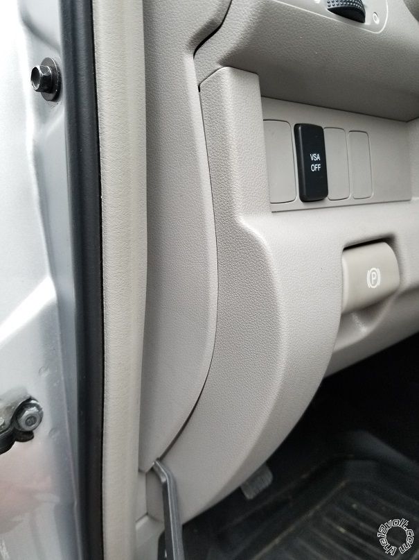
Use a non-marring trim tool to remove the dash side trim pictured below :
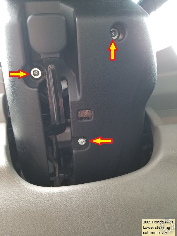
To remove the Steering Column covers, remove the three Phillips head screws at the underside of the
steering column shown below :
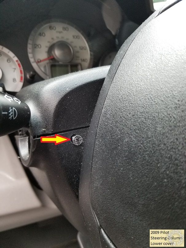
Next remove the two screws at the 9 and 3 O'clock position by rotating the steering wheel to expose
these hidden screws indicated below :
Separate the two cover halves and remove.
Wires :
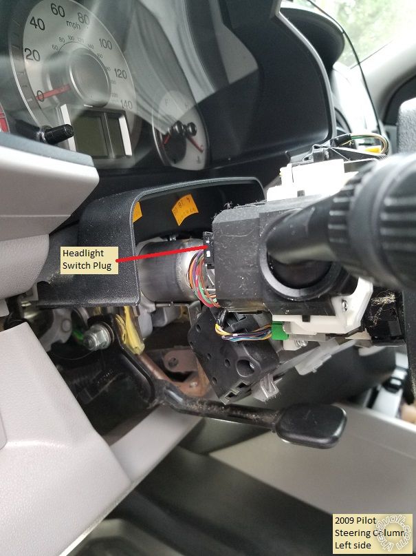
Below is a photo of the left side of the steering column showing the Headlight Switch connector :
This is a picture of the Headlight switch plug removed from the connector with the needed wires marked :
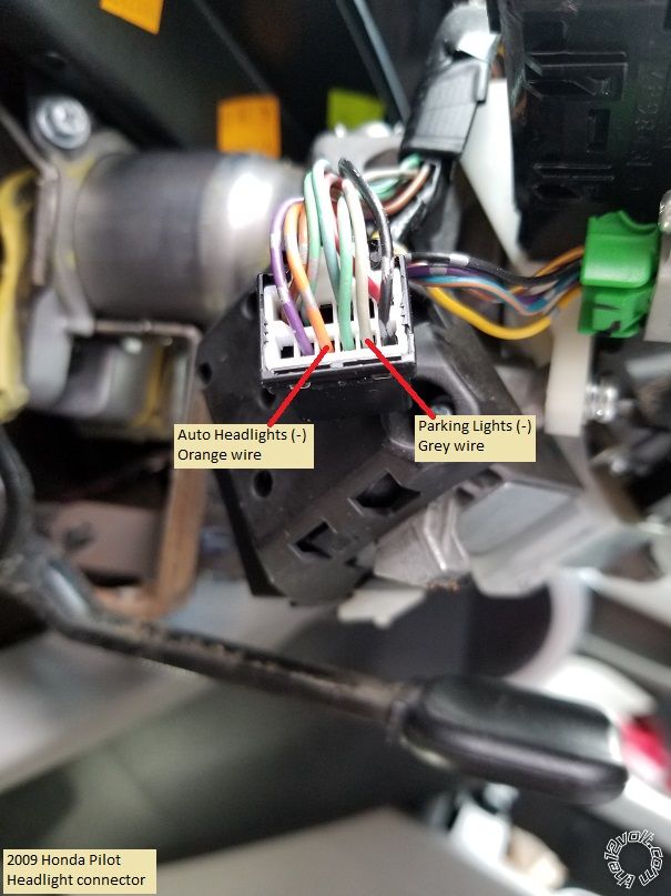
Please note that the Orange AutoHeadlight wire shown is used to ensure the Headlights turn off after
a R/S shutdown due to time-out or remote shutdown at night. Connect the R/S systems (-) GWR wire
to the Orange wire.
Next is a photo of the right side of the steering column with the needed connectors marked.
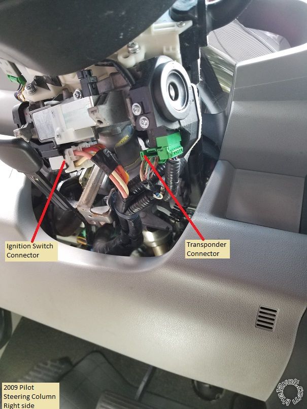
Here is a picture of the main ignition connector from Fortin with the ignition wires marked :
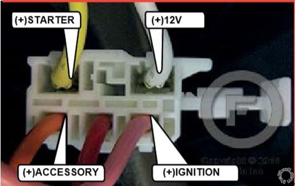
Please note that the Red wire is an Accessory type wire and not needed for this installation.
Below is the Transponder connector removed from its' plug with the necessary wires indicated :
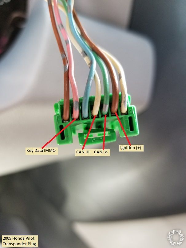
If you want to make the R/S Horn connection, that plug can be found at the top of the steering column.
Here is a photo :
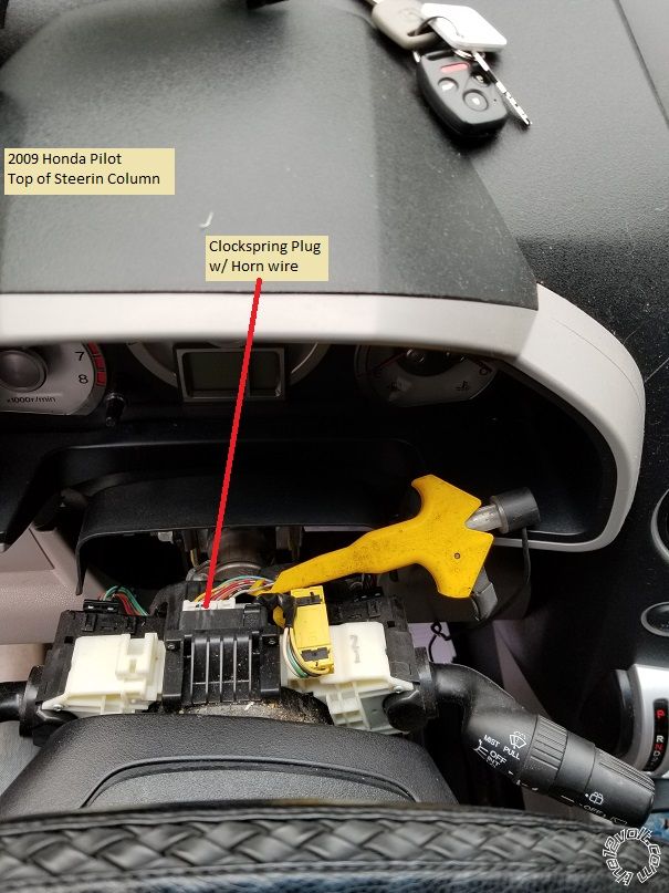
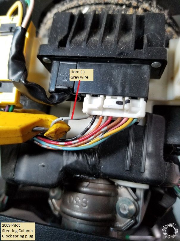
Below is a close-up of the plug with the Horn wire indicated:
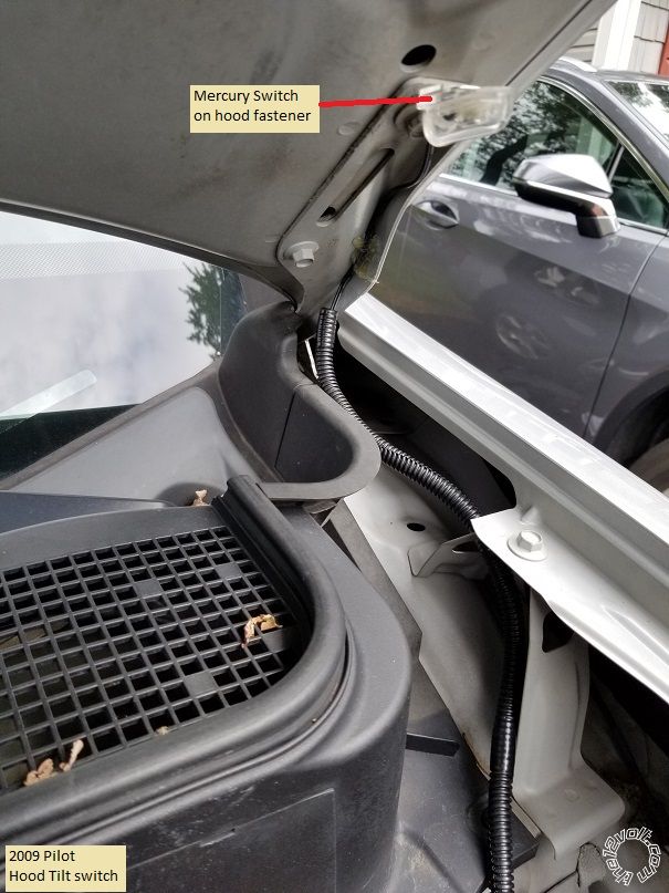
As noted, this Pilot had the Factory Alarm system but no Hood Pin switch. The APS57E Hood Pin
wire was passed through the firewall and connected to a mercury tilt switch, as shown below :
Notes :
The FLCAN was flashed with the ADS AL (DL) HA3 firmware and set to Data Mode. The APS57E
was programmed to ADS protocol for proper D2D communication. Going D2D between the APS57E
and the FLCAN eliminated many wires. Below is an updated Install Guide for the FLCAN using
D2D :
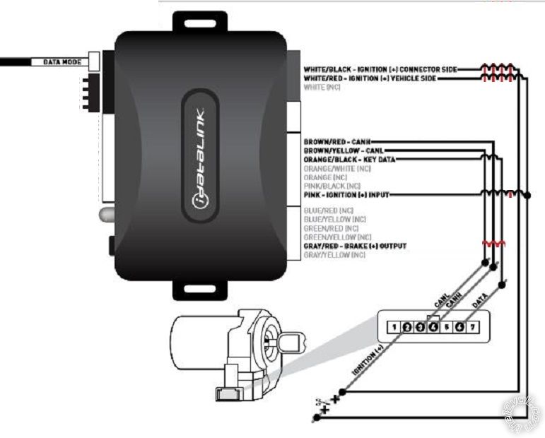
Only 6 wires are actually used and only 5 are connected to the vehicle.
The ADS AL (DL) HA3 firmware provides for a Disarm output, so it is not necessary to set either
the R/S system or the bypass module to "Unlock Before and Lock After R/S".
If you use an APS57E, here is the necessary wiring :
APS57E wiring :
Main Ignition Plug
1 Blue (Ign 1)..................................................................Pink at Pilot main ignition switch plug
2 Red/White (+ 12VDC Relays Ign 1 & Ign 2)......….....White at Pilot main ignition switch plug
3 Green (Ign 2)...............................................................Not Used
4 Purple (Accessory).......................................................Orange at Pilot main ignition switch plug
5 Red (+ 12VDC Relays ACC & Start).........................White at Pilot main ignition switch plug
6 Yellow (Starter).............................................................Yellow at Pilot main ignition switch plug
4 Pin plug
White (Parking Light Relay Output)..............................Grey at Pilot Headlight plug
Black (Chassis Ground)..................................................Chassis Ground
Yellow/Black (To controlling Alarm’s Ign Input)............Not Used
White/Red (Parking Light Relay Input).........................Chassis Ground
14 Pin plug
Black/White (- Horn Output)....................................................Grey at Pilot Clockspring plug
Gray/Black (- Inhibit/Shut Down From Hood Switch)..............to Mercury Tilt switch mounted on hood hinge bolt
LT. Blue (Ground Out While Running).....................................Orange at Pilot Headlight plug
all other wires in this connector are not used
D2D harness to FLCAN
Antenna harness to antenna
Soldering is fun!
 Printable version


 To remove the Steering Column covers, remove the three Phillips head screws at the underside of the
steering column shown below :
 Next remove the two screws at the 9 and 3 O'clock position by rotating the steering wheel to expose
these hidden screws indicated below :
 Separate the two cover halves and remove.
Wires :
Below is a photo of the left side of the steering column showing the Headlight Switch connector :
 This is a picture of the Headlight switch plug removed from the connector with the needed wires marked :
 Please note that the Orange AutoHeadlight wire shown is used to ensure the Headlights turn off after
a R/S shutdown due to time-out or remote shutdown at night. Connect the R/S systems (-) GWR wire
to the Orange wire.
Next is a photo of the right side of the steering column with the needed connectors marked.
 Here is a picture of the main ignition connector from Fortin with the ignition wires marked :
 Please note that the Red wire is an Accessory type wire and not needed for this installation.
Below is the Transponder connector removed from its' plug with the necessary wires indicated :
 If you want to make the R/S Horn connection, that plug can be found at the top of the steering column.
Here is a photo :
 Below is a close-up of the plug with the Horn wire indicated:
 As noted, this Pilot had the Factory Alarm system but no Hood Pin switch. The APS57E Hood Pin
wire was passed through the firewall and connected to a mercury tilt switch, as shown below :
 Notes :
The FLCAN was flashed with the ADS AL (DL) HA3 firmware and set to Data Mode. The APS57E
was programmed to ADS protocol for proper D2D communication. Going D2D between the APS57E
and the FLCAN eliminated many wires. Below is an updated Install Guide for the FLCAN using
D2D :
 Only 6 wires are actually used and only 5 are connected to the vehicle.
The ADS AL (DL) HA3 firmware provides for a Disarm output, so it is not necessary to set either
the R/S system or the bypass module to "Unlock Before and Lock After R/S".
If you use an APS57E, here is the necessary wiring :
APS57E wiring :
Main Ignition Plug
1 Blue (Ign 1)..................................................................Pink at Pilot main ignition switch plug
2 Red/White (+ 12VDC Relays Ign 1 & Ign 2)......….....White at Pilot main ignition switch plug
3 Green (Ign 2)...............................................................Not Used
4 Purple (Accessory).......................................................Orange at Pilot main ignition switch plug
5 Red (+ 12VDC Relays ACC & Start).........................White at Pilot main ignition switch plug
6 Yellow (Starter).............................................................Yellow at Pilot main ignition switch plug
4 Pin plug
White (Parking Light Relay Output)..............................Grey at Pilot Headlight plug
Black (Chassis Ground)..................................................Chassis Ground
Yellow/Black (To controlling Alarm’s Ign Input)............Not Used
White/Red (Parking Light Relay Input).........................Chassis Ground
14 Pin plug
Black/White (- Horn Output)....................................................Grey at Pilot Clockspring plug
Gray/Black (- Inhibit/Shut Down From Hood Switch)..............to Mercury Tilt switch mounted on hood hinge bolt
LT. Blue (Ground Out While Running).....................................Orange at Pilot Headlight plug
all other wires in this connector are not used
D2D harness to FLCAN
Antenna harness to antenna


