the12volt.com spacer
icon

2015 Nissan Altima PTS, Viper 4806V 2-Way


Post ReplyPost New Topic
< Prev Topic Next Topic >
aguilarpro 
Member - Posts: 31
Member spacespace
Joined: October 17, 2015
Location: Indiana, United States
Posted: November 19, 2019 at 7:56 PM / IP Logged Link to Post Post Reply Quote aguilarpro
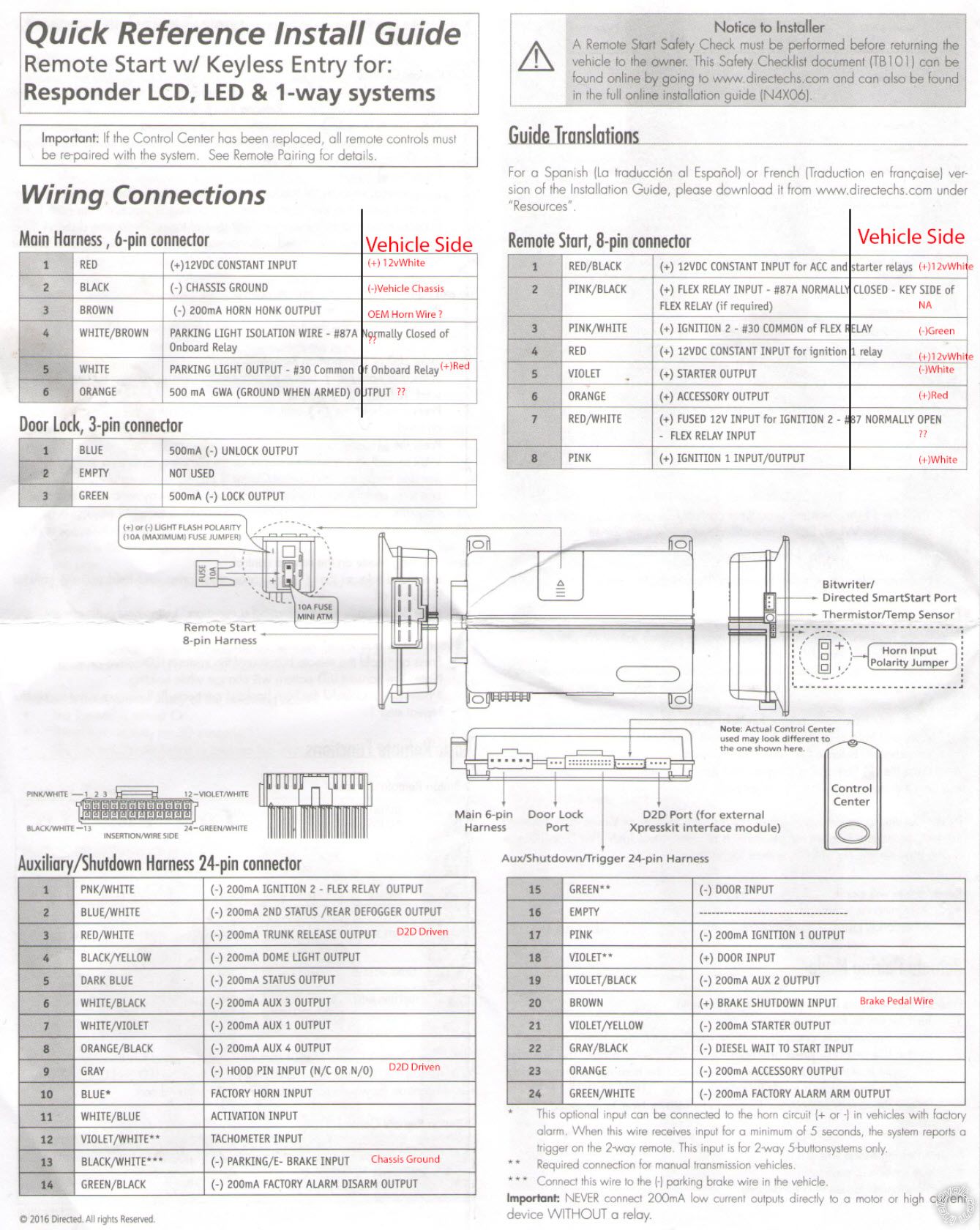
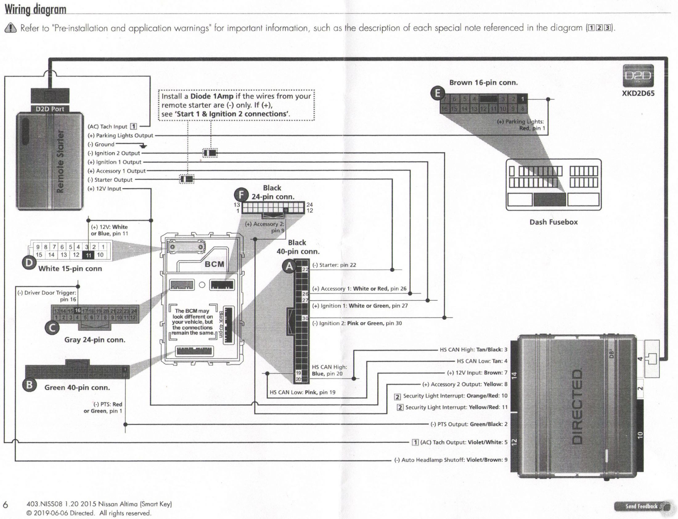
I'm hoping someone can check my work here. I'm in the process installing this alarm on my Nissan Altima 2015 Push To Start. I have everything almost gathered up but I have some doubts as what else is needed to be connected on the alarm side. I have the DB3 bypass module along with the wiring applicable to the vehicle so I'm covered there and partial wiring from the Remote start side. I have highlighted the wire I will be connecting based on the diagram provided with the DBALL 3 but I do not have the complete schematics and I believe I'm still missing some basic connections. Also, the use of Diodes appears to not be necessary in my case but mentions to see "Start 1 & Ignition 2 Connections" which in this case Ign2 is marked with a Diode but the Alarm side is positive. I appreciate any help that I can get.
2015 Nissan Altima PTS, Viper 4806V 2-Way -- posted image.
Honda Accord 2008 EX-L 2.4 S
aguilarpro 
Member - Posts: 31
Member spacespace
Joined: October 17, 2015
Location: Indiana, United States
Posted: November 20, 2019 at 10:20 PM / IP Logged Link to Post Post Reply Quote aguilarpro
Let me know if you guys have installed or are familiar with this system, I appreciate any help I can get. Thanks!
Honda Accord 2008 EX-L 2.4 S
dcman41 
Copper - Posts: 211
Copper spaceThis member has made a donation to the12volt.com. Click here for more info.spacespace
Joined: October 21, 2005
Location: United States
Posted: November 22, 2019 at 12:59 PM / IP Logged Link to Post Post Reply Quote dcman41
in your situation you will be using both + and - polarity for your ignition wires. no relays are needed because your remote start brain supports both. use the respective wires on the 24 pin harness with a diode placed in line and the stripe facing towards the remote star on all negative polarity ignition wires. Use Pin 1 / 24 (pink/white ) - ignition 2 flex output. Pin 21/24 (violet / yellow) - starter output . Use the heavy the gauge harness pink wire for + ignition and orange for + accessory. good luck, hope this helps
dcman41 
Copper - Posts: 211
Copper spaceThis member has made a donation to the12volt.com. Click here for more info.spacespace
Joined: October 21, 2005
Location: United States
Posted: November 23, 2019 at 7:26 AM / IP Logged Link to Post Post Reply Quote dcman41
only connect the wires shown in the DB3 diagram. your db3 bypass will handle your brake shutdown, door locks, trunk release, etc...
aguilarpro 
Member - Posts: 31
Member spacespace
Joined: October 17, 2015
Location: Indiana, United States
Posted: December 02, 2019 at 8:06 PM / IP Logged Link to Post Post Reply Quote aguilarpro
So, if I'm reading this right, I don't need wires 2, 3, 5 & 7 from Remote Start, 8-pin connector? What about Main harness 6-pin connector(Do I need wire 4 - White/Brown)?
Honda Accord 2008 EX-L 2.4 S
dcman41 
Copper - Posts: 211
Copper spaceThis member has made a donation to the12volt.com. Click here for more info.spacespace
Joined: October 21, 2005
Location: United States
Posted: December 05, 2019 at 9:51 AM / IP Logged Link to Post Post Reply Quote dcman41
yes, that is correct, you don’t need the wires you specified and you also don’t need the white/brown wire either
aguilarpro 
Member - Posts: 31
Member spacespace
Joined: October 17, 2015
Location: Indiana, United States
Posted: December 06, 2019 at 4:56 PM / IP Logged Link to Post Post Reply Quote aguilarpro
Does the heavy wires (ing & acc, 8-pin) go to those small wires at the car computer? Or should I use those from the 24 pin? They have different polarities however as can be seen in the diagrams.
Honda Accord 2008 EX-L 2.4 S
aguilarpro 
Member - Posts: 31
Member spacespace
Joined: October 17, 2015
Location: Indiana, United States
Posted: December 07, 2019 at 3:33 PM / IP Logged Link to Post Post Reply Quote aguilarpro
I installed the heavy gauge wires to the small ones and right now I'm getting "I-Key System Error: See Owner's Manual" when attempting remote start. I know this is not the bypass causing it as I have the key close and it still says the same thing. It perhaps is a wire from the bypass that needs something else. As illustrated above, I did not wire the ones with the #[2] symbols on the 12-pin connector of the D2D, perhaps this is where my problem lies.
Honda Accord 2008 EX-L 2.4 S
aguilarpro 
Member - Posts: 31
Member spacespace
Joined: October 17, 2015
Location: Indiana, United States
Posted: December 09, 2019 at 6:59 PM / IP Logged Link to Post Post Reply Quote aguilarpro
dcman41 wrote:
yes, that is correct, you don’t need the wires you specified and you also don’t need the white/brown wire either
I'm suspecting this could be a hood latch that is preventing a remote start since this is a D2D option? Please let me know what you think. I see that the remote flashes Red & Orange during remote start process and then Flashing green for actuating the brain to remote start but then it gets the I-Key error and then tries again 2 more times with a total of 3 times. Thanks in advance.
Honda Accord 2008 EX-L 2.4 S
aguilarpro 
Member - Posts: 31
Member spacespace
Joined: October 17, 2015
Location: Indiana, United States
Posted: January 21, 2020 at 12:15 PM / IP Logged Link to Post Post Reply Quote aguilarpro
Somebody please help :(
Honda Accord 2008 EX-L 2.4 S
Page of 2

  Printable version Printable version Post ReplyPost New Topic
You cannot post new topics in this forum
You cannot reply to topics in this forum
You cannot delete your posts in this forum
You cannot edit your posts in this forum
You cannot create polls in this forum
You cannot vote in polls in this forum

  •  
Search the12volt.com
Follow the12volt.com Follow the12volt.com on Facebook
Thursday, April 25, 2024 • Copyright © 1999-2024 the12volt.com, All Rights Reserved Privacy Policy & Use of Cookies
Disclaimer: *All information on this site ( the12volt.com ) is provided "as is" without any warranty of any kind, either expressed or implied, including but not limited to fitness for a particular use. Any user assumes the entire risk as to the accuracy and use of this information. Please verify all wire colors and diagrams before applying any information.

Secured by Sectigo
the12volt.com spacer
Support the12volt.com
Top
the12volt.com spacer