Q1 If you look at the wire listings* for a bunch of different cars,
you will notice that some do have 2 Ignition wires, some have
2 Accessory wires and some even have 2 Starter wires. Each
type of wire has a specific job to do and each can be tested for
its' function. i.e. A starter wire will only have power when the
starter motor is cranking the engine., an Ignition wire will have
power all the time the engine is running. When the vehicle is
designed, the engineers will incorporate multiple ignition wires
if they feel it's necessary. When installing a remote starter unit
we usually try to duplicate what happens during a normal key
start. If a vehicle has 2 Accessory wires, each one is a separate
circuit and the R/S unit should provide the same type of isolation.
Your vehicle is pretty basic with just one of each. The Viper is
designed to be generic and able to handle many different vehicles.
Having a program selectable extra high current ignition output
is a good feature. In your case it is not needed. There will be
many Viper wires and features that are not needed for your
specific vehicles needs.
* Bulldog Security : http://www.bulldogsecurity.com/bdnew/vehiclewiringdiagrams.aspx
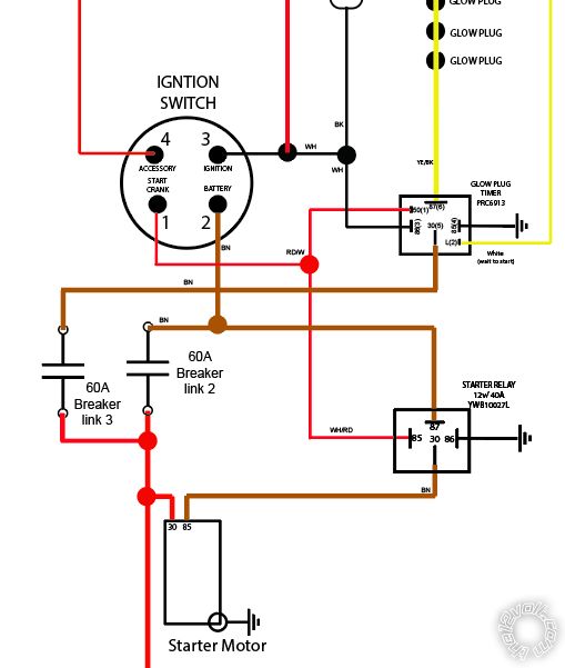
Q2 The thick Red wire at Pin 5 of the 10 Pin connector supplies
power for the IGN1 Pink output. The slightly thinner Red wire at
Pin 1 of the 6 Pin connector supplies power for the brain and (+)
Parking Light output, among other things. The fact that your
vehicle has a 60 Amp supply feed to Pin 2 of the ignition switch
means that the total power needed for all ignition switch outputs
is 60 Amps. This includes the Ignition and Accessory circuits on
Pins 3 and 4. Remember that while this 60 Amp circuit supplies
the Starter motor control relay, the ACC circuit drops while the
Starter output is ON. The internal relays in the Viper should be
able to handle 30 Amps. If you were to test the actual vehicle
Accessory max current draw, it would be less than 60 Amps, as
some of that 60 Amp supply is being used by the Ignition circuit.
Q3 See Q2
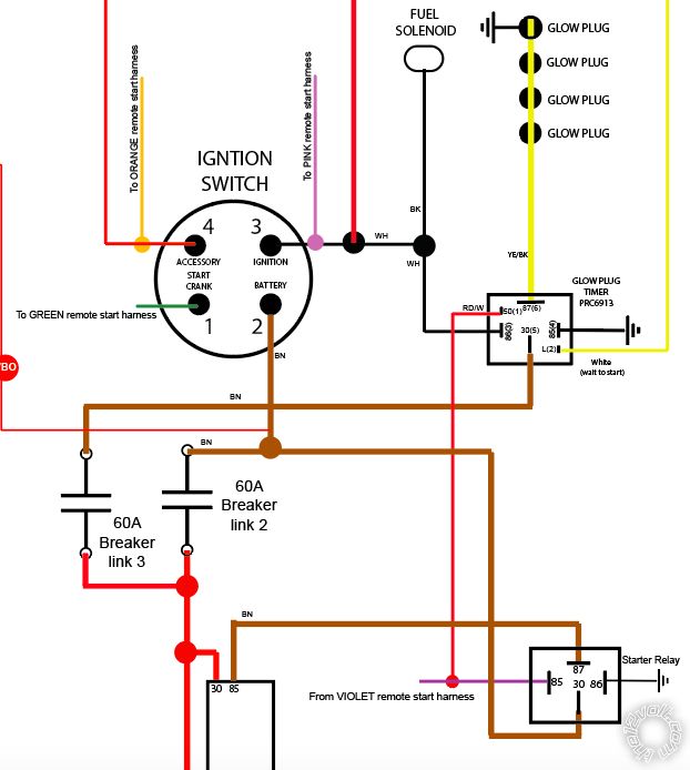
Q4 Anti-grind is like Geepherder said, it will prevent the starter
motor from engaging under R/S if the driver inadvertently turns
the key to START during R/S key take-over. It's just a nice add-on
for those that don't pay attention, can't hear the engine running
or don't bother to look at the Tach. During normal vehicle operation
( not using the Viper ), everything is normal and the ignition switch
has the same functions. The cut vehicle Starter wire goes through
the Viper internal relay Green wire ( 87a ) to Purple wire ( 30 ).
The Starter-Kill portion is where the Starter wire is left open
when the vehicle is locked/armed. If someone breaks into the vehicle
and manages to turn the ignition switch to Start the Vipers internal
relay will open the cut Starter wire to prevent cranking. Study the
relay diagrams and info for relay operation and pin usage.
Q5 While you think of this a strickty an output to power the vehicles
Ignition circuit during R/S run time, the Viper uses it for other purposes.
The Viper will monitor this wire and if it sees +12V it figues that the key
is in the ignition switch and in the RUN or START positions. With a Viper
alarm system, if the vehicle locked/armed and the ignition circuit goes
to +12V, it's time to turn on the siren - someone is trying to steal the
vehicle. On some Viper units the ignition circuit is monitored and used
during R/S controller programming. Also, if the Viper gets a remote
start command from the Viper FOB, it will check to see if the Hood
is open, the brake pedal is depressed or the Ignition circuit has +12V.
Any of these conditions will prevent a R/S. That is where the Input
function comes from for the thick Pink wire.
Soldering is fun!


 Printable version


