You can do a 3X Lock with the EVO-ONE and DC3 systems. They are looking for (-) Activation signal so a relay would be needed to change the Lock Motor GRAY(+) @ DRIVER WINDOW SWITCH BLACK 26 PIN CONN, PIN 21 signal to the (-) needed. This would involve running a wire into the drivers door.
The CS925-S unit has a (+) Activation Input so it could be wired directly to the above mentioned Lock Motor wire. No relay needed. Some programming would be required to assign the number of lock pulses needed to trigger a R/S.
As for Installation Manuals :
Here is a link to the CS925-S ( CM900s) Install Guide : https://www.the12volt.com/installbay/file.asp?ID=1420
Here is a wire chart for your install :
CM900-s to 2003 Tahoe
CN1
Pin 1 Red - Constant 12V ------------------------------------- Red +12V Constant
Pin 2 Green/White - Programmable Output --------------- not used
Pin 3 Red/White - Constant 12V ----------------------------- Red/Whire +12V Constant
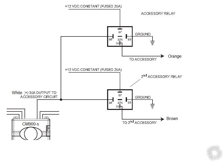
Pin 4 White - Accessory 12V positive (+) ------------------- See ACC relay diagram below
Pin 5 Blue - Programmable Output set to IGN2 ---------- White
Pin 6 Yellow - Starter 12V positive (+) ---------------------- Yellow
Pin 7 Green - Ignition 12V positive (+) ---------------------- Pink
Pin 8 Black - Ground negative (-) input --------------------- Chassis Ground
CN3
Pin 1 Green/White - (fixed) Parking light 250mA negative (-) output ----------- Gray/Black in Brown BCM plug
Pin 2 Blue/Lt. Green - [POC 2] Lock 250mA, 800mS (-) negative output ----- not used
Pin 3 Blue - [POC 3] Unlock 250mA, 800mS (-) negative output ---------------- not used
Pin 4 Black - [POC 4] Status/GWR 250mA latched negative (-) output -------- not used
Pin 5 Orange - [POC 5] Factory Alarm Arm (FAA) (-) output -------------------- not used
Pin 6 Orange/White - [POC 6] Factory Alarm Disarm (FAD) (-) output -------- not used
Pin 7 White - [POC 7] Horn:250mA negative (-) output --------------------------- Black at Gray BCM Plug
Pin 8 Gray/Black - Hood Pin negative (-) (default setting) input ----------------- to kit supplied hood pin
Pin 9 Light Blue/White - Brake 12V positive (+) input ----------------------------- White at Brake pedal switch
Pin 10 RED/White - Trigger start (-) input -------------------------------------------- not used
Pin 11 RED - Positive (+) input --------------------------------------------------------- GRAY(+) @ DRIVER WINDOW SWITCH BLACK 26 PIN CONN, PIN 21
Pin 12 Yellow/Black - Engine sensing input (A/C) ----------------------------------- White @ Instrument Cluster plug
Blade connector plug
Pin 4 Orange J1850 Data --------------------------------- ODB2 Violet @ Pin 2
ACC relay diagram ( need two 30/40 Amp SPDT relays with 5 pin harness and 2 in-line fuse holders w/20 Amp fuses )
 Soldering is fun!


 Cheers,
Kreg
Cheers,
Kreg
 Printable version


