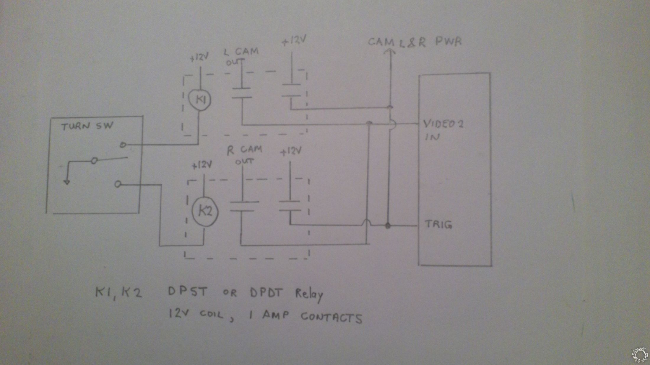
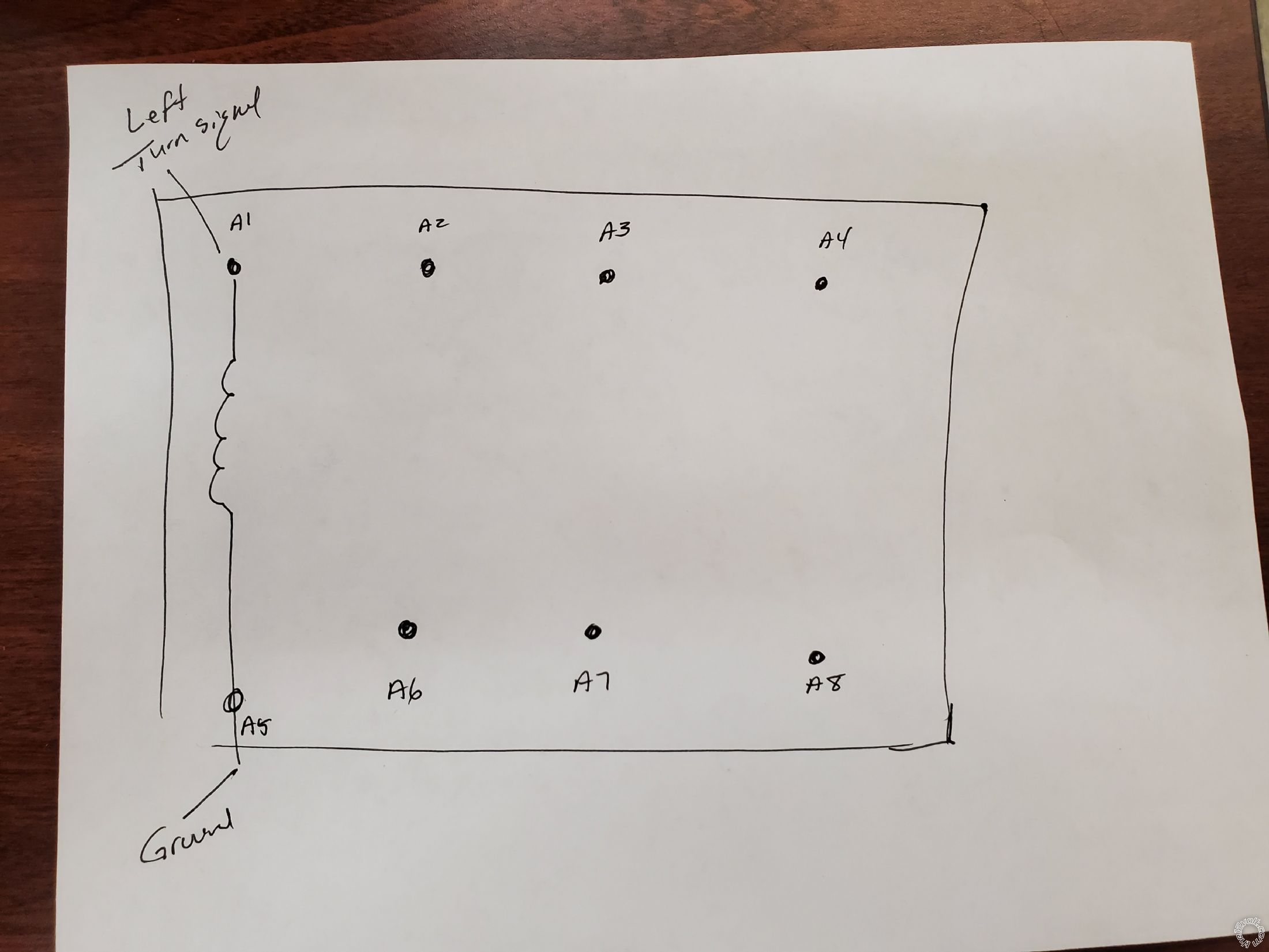
the12volt.com spacer
icon

Two Triggers, One Output


Post ReplyPost New Topic
< Prev Topic Next Topic >
kniggt3136 
Member - Posts: 9
Member spacespace
Joined: October 20, 2020
Location: New York, United States
Posted: October 21, 2020 at 2:34 PM / IP Logged Link to Post Post Reply Quote kniggt3136
Brand: BOYO VISION
BOYO VTM700M - Clip-on Rear-View Mirror with 7" TFT-LCD Backup Camera Monitor
kniggt3136 
Member - Posts: 9
Member spacespace
Joined: October 20, 2020
Location: New York, United States
Posted: October 21, 2020 at 10:44 PM / IP Logged Link to Post Post Reply Quote kniggt3136
I was thinking over and I think 4 relays will do it.
Relay 1
86 - left turn signal
85- ground
87A- nothing
30 - ACC
87 - Power on left camera and connect to pin 87A from Relay 4
Relay 2
86 - Right turn signal
85- ground
30 - ACC
87A- nothing
87 - power right camera, connected to pin 86 of relay 3 and pins 86 and 87 of relay 4
Relay 3
86 - receives from relay 2
85 ground
87a- RCA to left camera
87- Rca to right camera
30 - Video input to mirror
Relay 4
86 - receives input from relay 2
85- ground
87a - receives input from pin 87 from relay 1 that will go to pin 30
87 - receives input from pin 87 from relay 2
30 - connected to trigger cable of the mirror.
So when I click on the left turn signal in will go to relay 1 pin 86 sending 12V to camera and 87a of relay 4 that will go to pin 30 of relay 4 causing it to trigger the mirror. The camera will send video to pin 87A of relay 3 going to pin 30 of relay 3 going to the input of the cable.
Now when i click on the right turn signal it goes to relay 2 causing pin 87 of relay 2 to send 12V to pin 86 of relay 3 and 12v to pins 86 and 87 of relay 4, it will also send 12V to camera which would send video to pin 87 of relay 4 that would send it to pin 30 of relay 3 which would send video to input to the camera. As stated before pin 87 of relay 2 will send 12V to pins 86 and 87 of relay 4 causing the switch to close causing 12V to go the trigger cable of the mirror.
Let me know what you think.
i am an idiot 
Platinum - Posts: 13,663
Platinum spaceThis member consistently provides reliable informationspace
Joined: September 21, 2006
Location: Louisiana, United States
Posted: October 22, 2020 at 7:12 AM / IP Logged Link to Post Post Reply Quote i am an idiot
I will look at it and evaluate this evening.
eguru 
Copper - Posts: 340
Copper spacespace
Joined: February 04, 2018
Location: Quebec, Canada
Posted: October 22, 2020 at 7:39 AM / IP Logged Link to Post Post Reply Quote eguru
You can use 2 small DPST or DPDT relays as per photo.
Don't go oversize on the relay contact current ratings as they don't handle video signals very well.Two Triggers, One Output - Page 2 - Last Post -- posted image.
kniggt3136 
Member - Posts: 9
Member spacespace
Joined: October 20, 2020
Location: New York, United States
Posted: October 22, 2020 at 8:09 AM / IP Logged Link to Post Post Reply Quote kniggt3136
Do you think you can find a video on youtube that will show what i need to do RCAs cables to connect them to the relay?
But do you think may way will work?
eguru 
Copper - Posts: 340
Copper spacespace
Joined: February 04, 2018
Location: Quebec, Canada
Posted: October 22, 2020 at 10:18 AM / IP Logged Link to Post Post Reply Quote eguru
Two general purpose relays like this are all you need plus 2 cables with RCA M/F connectors.
https://abra-electronics.com/electromechanical/relays/pcb-mtg-1a-2a/rdp-145-mini-dip-relay-12vdc-1a-dpdt-rdp-145.html
Cut the cables and use the female ends to connect to the RCA plugs from the 2 cameras and wire the center conductor to each of the two relays.
Use the male end of the cable to connector to your mirror and wire the center conductor to the junction of the 2 relay contacts.
The outer cable conductors just get soldered together.
kniggt3136 
Member - Posts: 9
Member spacespace
Joined: October 20, 2020
Location: New York, United States
Posted: October 22, 2020 at 1:37 PM / IP Logged Link to Post Post Reply Quote kniggt3136
Base on the below drawings can you write what cables i need to connect to each relay. Using relays for the first time.Two Triggers, One Output - Page 2 - Last Post -- posted image.
Taking relay 1
A1- Left turn signal
A2- 12v from battery
A3 - Empty
A4- 12v to the camera and 12v to trigger
A5- ground
A6- rca cable from camera
A7- empty
A8- video out to mirror
eguru 
Copper - Posts: 340
Copper spacespace
Joined: February 04, 2018
Location: Quebec, Canada
Posted: October 23, 2020 at 7:23 AM / IP Logged Link to Post Post Reply Quote eguru
You need to wire the relay coils directly to the turn switch (not to the pulsing 12V to the bulbs). On most vehicles activating the turn switch grounds the input to the BCM so that is the way I have shown it in the schematic. Meter your switch to verify that it is switching ground and not 12V.
btw. You might consider leaving the 2 cameras powered up continuously because there may be excessive delay for them to power up properly and stabilize each time you apply the turn switch.
eguru 
Copper - Posts: 340
Copper spacespace
Joined: February 04, 2018
Location: Quebec, Canada
Posted: October 31, 2020 at 7:48 AM / IP Logged Link to Post Post Reply Quote eguru
So did you get your project working successfully with the help you received from the members?
It is always nice for us to get feedback after expending energy to provide help.
Page of 2

If you wish to post a reply to this topic, you must first login.
If you are not already registered, you must first register.

  Printable version Printable version Post ReplyPost New Topic
You cannot post new topics in this forum
You cannot reply to topics in this forum
You cannot delete your posts in this forum
You cannot edit your posts in this forum
You cannot create polls in this forum
You cannot vote in polls in this forum

  •  
Search the12volt.com
Follow the12volt.com Follow the12volt.com on Facebook
Tuesday, March 19, 2024 • Copyright © 1999-2024 the12volt.com, All Rights Reserved Privacy Policy & Use of Cookies
Disclaimer: *All information on this site ( the12volt.com ) is provided "as is" without any warranty of any kind, either expressed or implied, including but not limited to fitness for a particular use. Any user assumes the entire risk as to the accuracy and use of this information. Please verify all wire colors and diagrams before applying any information.

Secured by Sectigo
the12volt.com spacer
Support the12volt.com
Top
the12volt.com spacer