the12volt.com spacer
icon

Constant To Momentary Output Relay Diagram


Post ReplyPost New Topic
< Prev Topic Next Topic >
ewingr 
Copper - Posts: 60
Copper spacespace
Joined: February 21, 2007
Location: United States
Posted: August 11, 2021 at 1:56 PM / IP Logged Link to Post Post Reply Quote ewingr
I am needing to follow this diagram, I believe. Need to have a negative pulse sent when another wire recieves 12v. The 12v will stay on for a period, so I just need a quick negative pulse, then nothing.
According to the diagram I need a 1K uf capacitor and a 10k fixed resistor.
When I do a search on 1K uf resistor, I find various things such as: 
  • Safety Capacitor, Metallized PP, Radial Box - 2 Pin, 0.01 µF, ± 20%, X1, Through Hole
  • CAPACITOR, CERAMIC DISC, 390PF, 1KV, RAD ROHS COMPLIANT
  • Tantalum Capacitor 1 uF 35 Volt
I see different things they are made of, I see 1uf, not 1k uf etc.
The resister seems pretty straight forward. I even see small qty of those on Amazon.
If anyone can give me some feedback on specific search/specs for the resister it would be very much appreciated.
As well a source for a small qty. I realize that I would need to pay much more than a single value to warrant someone's time, but I could buy a quantity/kit of various ones, but then it's likely I'd not be sure which is which.
As you have guessed, I'm not educated on this stuff. 🤓 But I'll be able to follow the diagram and solder it together. Which makes me realize I'll probably need to find a sandal plastic box two contain it.
Thanks
Roger
ewingr 
Copper - Posts: 60
Copper spacespace
Joined: February 21, 2007
Location: United States
Posted: August 11, 2021 at 2:01 PM / IP Logged Link to Post Post Reply Quote ewingr
I suppose I should list what I'm doing with this: need to send a negative pulse to a wire to unlock a door in an old car when I put the car into park. I have something providing a positive output when I put it in park which remains on until taken out of park or ignition turned off. I have the negative wire that I would use to send the negative pulse to unlock the car. So I just need to build this resistor, relay, capacitor setup to handle the work.
Thanks
Roger
wirewise 
Moderator - Posts: 489
Moderator spaceThis member has made a donation to the12volt.com. Click here for more info.spaceThis member consistently provides reliable informationspace
Joined: March 07, 2002
Location: California, United States
Posted: August 11, 2021 at 3:07 PM / IP Logged Link to Post Post Reply Quote wirewise
Try searching for a 1,000 microfarad capacitor, not a "1K uf resistor". You also need a 10,000 ohm resistor for the relay diagram you referenced.
~wirewise~ Verify all wiring with your meter before making any connections!
ewingr 
Copper - Posts: 60
Copper spacespace
Joined: February 21, 2007
Location: United States
Posted: August 12, 2021 at 5:11 PM / IP Logged Link to Post Post Reply Quote ewingr
Thank you so much. I think the syntax you gave me did the trick.
Thanks
Roger
ewingr 
Copper - Posts: 60
Copper spacespace
Joined: February 21, 2007
Location: United States
Posted: August 15, 2021 at 7:27 PM / IP Logged Link to Post Post Reply Quote ewingr
I am wantint to send a momentary negative output to a door unlock switch. I want it to be triggered by putting the car in park. I have a positive wire ouput when this happens, although it is constantly positive output until I turn the engine off.
This diagram from the 12Volt diagrams looks like what I need to do:
Constant To Momentary Output Relay Diagram -- posted image.
With only a curosory glance to get the capacitor and resister ordered I am now studying it a bit more to make it happen. But now I'm not so sure about this.
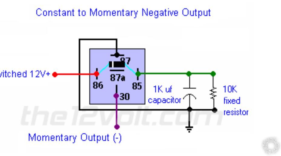
None of the wires are notated as the source positive wire in the diagram. I was assuming I'd put the wire that puts out the + when in park at 87. But looking at this diagram that goes to a gnd. I suppose that t86 being a switched 12v could be it. Given that the wire is not 12v 100% of the time...ie. it is hot when the care is in Park AND the ign on. So, just to verify, does that sound right?
The other thing, I'm no electronics builder. I had thought originally of putting the capacitor and resistor in series between 87 and 85. But I'm not thinking that is right. Do I need to make it physically as drawn? ie. 85 go a junction which also has GND and the capacitory, and a lead off that to the resister. Other end of resister goes to a wire to a junction with the capacitor, then a wire from there to 85.
Does that make sense, or am I bouncing into the ether?
Thanks
Roger
the12volt 
Administrator - Posts: 3,955
Administrator spaceThis member has made a donation to the12volt.com. Click here for more info.spaceThis member has been recognized as an authority in Electrical Theory. Click here for more info.spaceThis member has been recognized as an authority in Mobile Audio and Video. Click here for more info.spaceThis member has been recognized as an authority in Mobile Security and Convenience. Click here for more info.spacespace
Joined: March 07, 2002
Location: Louisiana, United States
Posted: August 16, 2021 at 11:39 AM / IP Logged Link to Post Post Reply Quote the12volt
Terminal 86 is connected to the 12V+ source. Terminal 87 is connected to ground as is the negative side of the capacitor and one side of the resistor. Do not wire the capacitor and resistor in series with terminal 87. Yes, you need to wire it as shown in my diagram. Terminal 30 will provide a momentary negative pulse when 12V+ is applied to terminal 86.
Constant To Momentary Output Relay Diagram -- posted image. the12volt • Support the12volt.com
ewingr 
Copper - Posts: 60
Copper spacespace
Joined: February 21, 2007
Location: United States
Posted: August 16, 2021 at 4:12 PM / IP Logged Link to Post Post Reply Quote ewingr
Thanks. Just finished up, and it works fine.
Thanks
Roger
ewingr 
Copper - Posts: 60
Copper spacespace
Joined: February 21, 2007
Location: United States
Posted: August 24, 2021 at 1:10 PM / IP Logged Link to Post Post Reply Quote ewingr
My door locks have quit working. I'm sure something I did wrong broke whatever is broken. I had attempted to implement an additional relay as described here, . I have pulled the additional relay out.
At any rate, there's 3 places to look for the problem: the pulse ouput to the actuators (from keyless unit); the door relays (the 451M receives the ouptut from the keykless unit); and finally the actuator itself.
So when I push the unlock button on the remote. I hear relays clicking, both under dash were the keyless unit sends the signal from, and the door relay (541M).
So given that, my initial thought is that the problem is the door lock actuators .
So, I made an access point to the blue wire and the green wire from the relay that feeds the actuators (541M). At each of those points, there is a junction where green from each relay and the wire down to the actuator are connected , and same for the blue. When I put a meter on that point, it shows 12V constant. When I take the keys away from the car, triggering a lock, the 12v has a short interuption of the 12V. That makes me feel like the relays are working.
The door actuators have only 2 wires, green for lock, and blue for unlock. I presume that the function of the 541M swaps the hot and hand gnd to make the actuators either lock or unlock.
I'm not sure whether the 541Ms or the actuators are the problem. Is a constant 12V at the green and blue wires going to the actuators normal? Any other thoughts?
Thanks
Roger
ewingr 
Copper - Posts: 60
Copper spacespace
Joined: February 21, 2007
Location: United States
Posted: August 26, 2021 at 8:44 PM / IP Logged Link to Post Post Reply Quote ewingr
Just in case someone interests in the details of the resolution...
The 541M can be either 12v constant, or Neg constant, depending on wheter in stalled in a positive or negative system, and how it's wired. So the 12v constant was NOT a problem.
I ended up pulling the door panels and getting to the actuators, and both were inoperable. New ones fixed my problem.
I'm not sure why they blew out. Maybe the settled on wiring from the main topic of this post allowed 12v constant to the units and it burned them up. Not going to tray that again.
Thanks
Roger

If you wish to post a reply to this topic, you must first login.
If you are not already registered, you must first register.

  Printable version Printable version Post ReplyPost New Topic
You cannot post new topics in this forum
You cannot reply to topics in this forum
You cannot delete your posts in this forum
You cannot edit your posts in this forum
You cannot create polls in this forum
You cannot vote in polls in this forum

  •  
Search the12volt.com
Follow the12volt.com Follow the12volt.com on Facebook
Friday, March 29, 2024 • Copyright © 1999-2024 the12volt.com, All Rights Reserved Privacy Policy & Use of Cookies
Disclaimer: *All information on this site ( the12volt.com ) is provided "as is" without any warranty of any kind, either expressed or implied, including but not limited to fitness for a particular use. Any user assumes the entire risk as to the accuracy and use of this information. Please verify all wire colors and diagrams before applying any information.

Secured by Sectigo
the12volt.com spacer
Support the12volt.com
Top
the12volt.com spacer