Here's a list of the connections I made into one page. It didn't copy very well from word so please excuse the weird format. I believe I had the Factory Disarm wire from the CM900 connected at one point to the GMDLBP but that was causing issues so I put it back to normal. Not having the ACC2 wire connected might explain why my starter went out last summer. Have you seen the ACC2 wire not connected cause that?
9-7x Wiring -> CM900 & GMDLBP
1. 9-7x - Orange 12v (30A) [+Trailer Brake Harness]
a. CM900 CN1 Pin 1 Red
b. CM900 CN1 Pin 3 Red/White
c. GMDLBP Red
2. 9-7x - Light Blue Brake Wire [+ Trailer Brake Harness]
a. CM900 CN3 Pin 9 Light Blue/White
3. 9-7x - Yellow Starter [+ Ignition Switch, Black 12 Pin Plug]
a. CM900 CN1 Pin 6 Yellow
4. 9-7x - Pink Ignition [+ Ignition Switch, Black 12 Pin Plug]
a. CM900 CN1 Pin 7 Green
5. 9-7x - White 2nd Ignition [+ Ignition Switch, Black 12 Pin Plug]
a. CM900 CN1 Pin 5 Blue
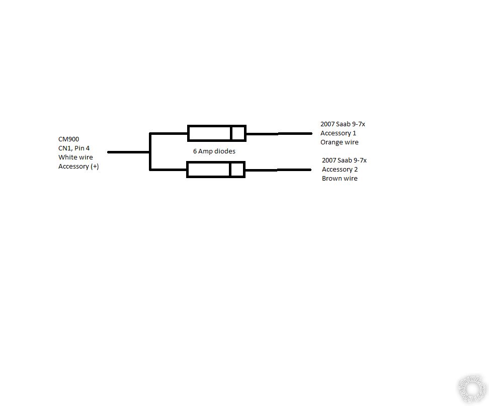
6. 9-7x - Orange Accessory 1 [+ Ignition Switch, Black 12 Pin Plug]
a. CM900 CN1 Pin 4 White [6 Amp Diode]
7. 9-7x Brown Accessory 2 [+ Ignition Switch, Black 12 Pin Plug]
a. CM900 CN1 Pin 4 White [6 Amp Diode]
8. 9-7x Light Green Keysense [- Ignition Switch, Black 12 Pin Plug]
a. CM900 CN3 Pin 4 Black [1N4001 Diode]
9. 9-7x Purple J1850 OBDII Serial Data [Data Link Connector]
a. GMDLBP Violet
10. 9-7x White Tachometer [AC Instrument Cluster]
a. CM900 CN3 Pin 12 Yellow
11. 9-7x Black/Yellow Horn Trigger [- Steering Column]
a. CM900 CN3 Pin 7 White
12. 9-7x Black Chassis Ground
a. CM900 CN1 Pin 8 Black
b. GMDLBP - Black
13. CM900 Black - CN3 Pin 4 [Status Ground]
a. GMDLBP Brown - Status Input [1N4001 Diode]
14. CM900 Blue/Green - Lock - CN3 Pin 2
a. GMDLBP Green Lock
15. CM900 Blue - Unlock - CN3 Pin 3
a. GMDLBP Blue Unlock
Thanks again for all of your help!
2007 Saab 9-7x 4.2


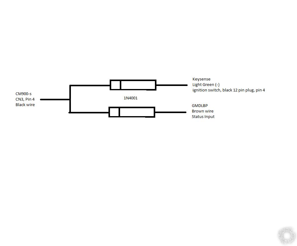
 For the Keysense wire you will use the CM900-s Black (-) GWR (Status Output) wire. It is already being used to control the GMDLBP bypass module so 1N4001 diodes are needed to provide isolation.
CN3
Pin 4 Black - [POC 4] (GWR) 250mA latched (-) output.......wire as per diagram below
Keysense....Light Green (-)....@ ignition switch, black 12 pin plug, pin 4
GMDLBP......Brown (-)..........Status Input wire
For the Keysense wire you will use the CM900-s Black (-) GWR (Status Output) wire. It is already being used to control the GMDLBP bypass module so 1N4001 diodes are needed to provide isolation.
CN3
Pin 4 Black - [POC 4] (GWR) 250mA latched (-) output.......wire as per diagram below
Keysense....Light Green (-)....@ ignition switch, black 12 pin plug, pin 4
GMDLBP......Brown (-)..........Status Input wire
 Printable version


