the12volt.com spacer
icon

2014 Kia Forte Koup, Standard Key, Manual Transmission, Compustar CM-X


Post ReplyPost New Topic
< Prev Topic Next Topic >
aceinny 
Member - Posts: 7
Member spacespace
Joined: February 05, 2024
Location: New York, United States
Posted: February 05, 2024 at 1:06 PM / IP Logged Link to Post Post Reply Quote aceinny
Looking for information on installing a Compustar CM-X with the Blade AL and DAS Sensor.
I can find all the wires needed in the vehicle but I'm not sure where they connect to the CM-X.
I have the ignition wires (High Current) but I don't see anywhere to connect the PARKING LIGHT (-) OUTPUT, STARTER 2 (+) OUTPUT.
Thanks in advance for any help.
2014 Kia Forte Koup, Standard Key, Manual Transmission, Compustar CM-X  -- posted image. 2014 Kia Forte Koup, Standard Key, Manual Transmission, Compustar CM-X  -- posted image. 2014 Kia Forte Koup, Standard Key, Manual Transmission, Compustar CM-X  -- posted image.
aceinny 
Member - Posts: 7
Member spacespace
Joined: February 05, 2024
Location: New York, United States
Posted: February 05, 2024 at 1:17 PM / IP Logged Link to Post Post Reply Quote aceinny
Also the car is originally from Canada so it does have the transponder chipped keys
kreg357 
Platinum - Posts: 7,783
Platinum spaceThis member has made a donation to the12volt.com. Click here for more info.spaceThis member has been recognized as an authority in Electrical Theory. Click here for more info.spaceThis member has been recognized as an authority in Mobile Security and Convenience. Click here for more info.spacespace
Joined: January 30, 2009
Location: Pennsylvania, United States
Posted: February 05, 2024 at 5:34 PM / IP Logged Link to Post Post Reply Quote kreg357
The CM-X is a nice unit but for your application you will need to change several programming options.
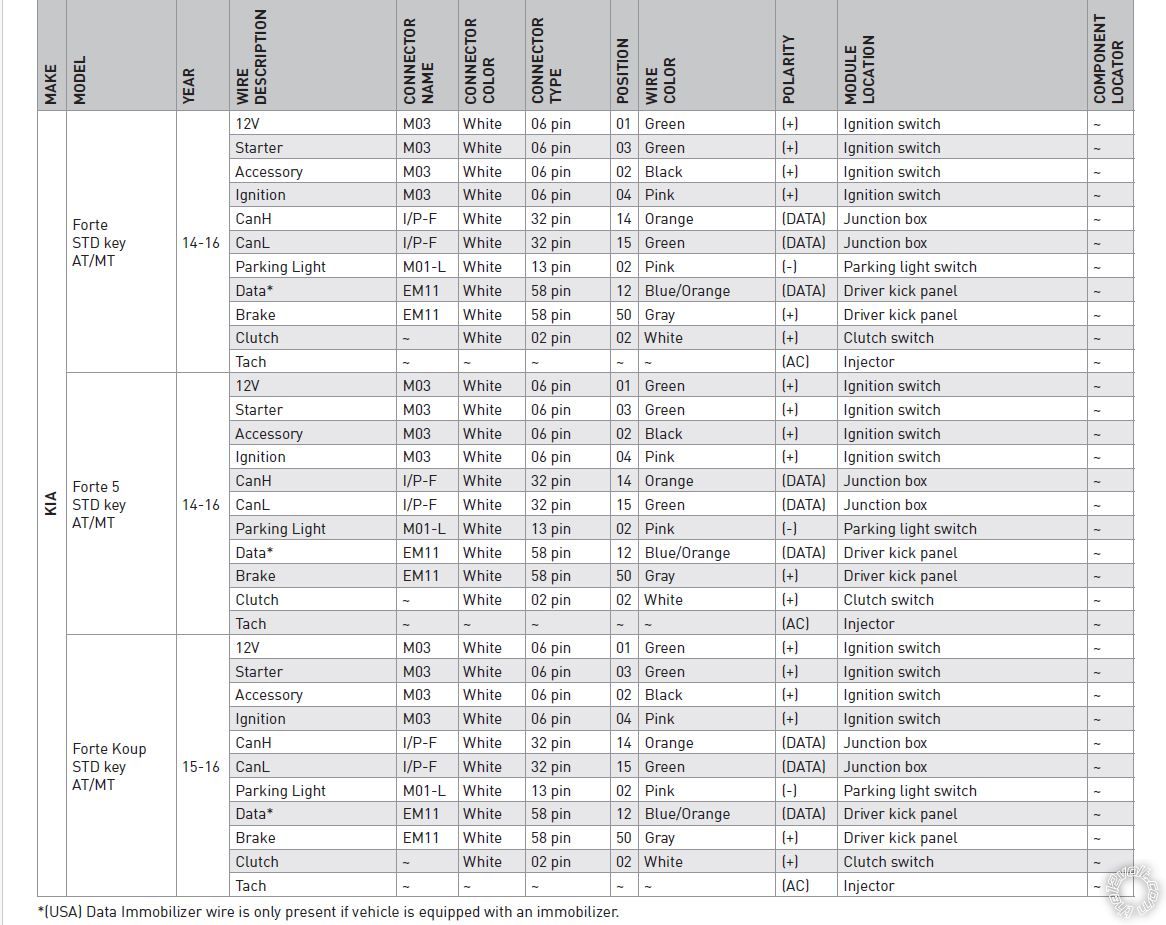
First a question. You said 2014 KIA Forte Koup? While I was able to select a 2014 through the FirsTech menus, when you open up the Blade AL Install guide it shows only 2015 and 2016 Koup, not a 2014. That could be a slight typo or something important, not sure.   Just strange that they don't list a 2014. As long as all the listed wire colors and locations are the same, you should be OK.
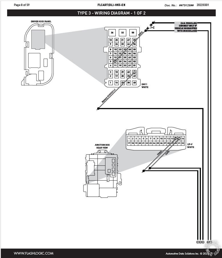
Next, the install guide you posted is for a FLCART not the Blade AL cartridge. The install document you should be using is #79127. Probably no differences but...
Anyway, the Blade AL cartridge must be flashed with the correct Blade AL(DL)-HK5 firmware.   If you have the ADS USB cable then you are all set. When you flash the firmware you can check/update the CM-X firmware to the latest version. Most importantly you can make the necessary changes to the CM-X options at that time.
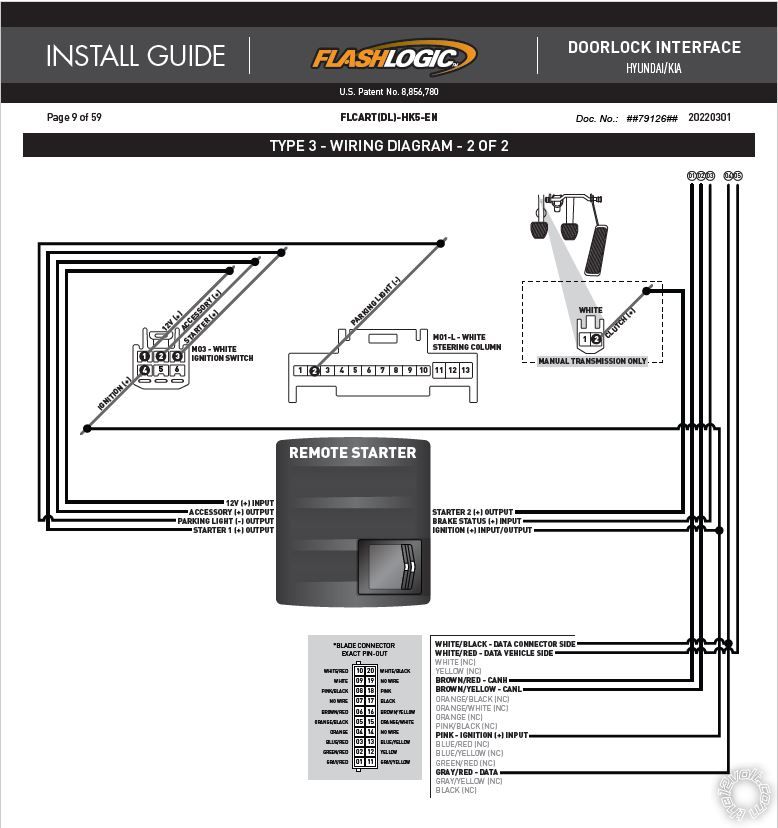
As you noticed, you need a Starter2 output from the CM-X to handle the clutch bypass. You need to change Special Option Group 4, Feature 3 to Option 2 (2nd Start). This will change the CN1 Blue wire at Pin 5 to a Starter type output for use as Starter2 to the clutch bypass.
For the needed (-) Parking Light output, you can re-assign POC #2. It is the White wire at CN4 Pin 3 that is for the Horn output, but with a Siren/Alarm you really don't need it. Change Special Option Group 3, Feature 2 to Option 1 (2nd Light). That will make the White wire a (-) Parking Light output.
Additionally, not shown on the Type 3 Install Diagram are the two fused +12V input wires, Red and Red/White. They both need to be connected to the cars' ignition switch. Use Pin 1 Green and Pin 5 Red, one wire to each. Also, the CN1 Black wire needs to go to a clean, solid chassis ground point. Verify that the vehicle has a factory hood pin for proper R/S and alarm functions to be supplied by the Blade-AL. If the R/S'd engine does not shut down when you pop the hood, install the kit supplied hood pin.
Soldering is fun!
aceinny 
Member - Posts: 7
Member spacespace
Joined: February 05, 2024
Location: New York, United States
Posted: February 06, 2024 at 6:49 AM / IP Logged Link to Post Post Reply Quote aceinny
Thanks for the quick reply and supplied information. I though it was weird that it doesn't list the 2014 but does pull up the HK5 information. I do have the ADS USB cable and have already updated the CM-x Firmware and flashed the Blade to the car.
I will go and change the options as needed to fit the vehicle. Any other recommended option changes?
Thanks again for the clarification.
aceinny 
Member - Posts: 7
Member spacespace
Joined: February 05, 2024
Location: New York, United States
Posted: February 06, 2024 at 6:57 AM / IP Logged Link to Post Post Reply Quote aceinny
One other question, do you know where the Tach wire goes and which is the best option (the manual says not to use Tachless mode for Manual Transmissions) to use for the Tach.
kreg357 
Platinum - Posts: 7,783
Platinum spaceThis member has made a donation to the12volt.com. Click here for more info.spaceThis member has been recognized as an authority in Electrical Theory. Click here for more info.spaceThis member has been recognized as an authority in Mobile Security and Convenience. Click here for more info.spacespace
Joined: January 30, 2009
Location: Pennsylvania, United States
Posted: February 06, 2024 at 7:54 AM / IP Logged Link to Post Post Reply Quote kreg357
For a M.T. install you must run in Tach Mode.
For the Tach signal you can go to a F.I. or a Spark Plug Coil Pack. I've even used a Cam Sensor on those cars. Here is Tach info from one source :
Tach Signal   NOT BLUE    AT IGNITION COILS BLACK 2 PIN CONNECTOR, PIN 1
Typically, at each coil pack or F.I. there are two wires. One wire is a common color to all and the other wires' color is unique to each cylinder. Use the unique colored wire.
You will have to go through the Tach Learn Process before attempting a R/S.
Soldering is fun!
aceinny 
Member - Posts: 7
Member spacespace
Joined: February 05, 2024
Location: New York, United States
Posted: February 09, 2024 at 9:46 PM / IP Logged Link to Post Post Reply Quote aceinny
Everything makes sense and I'm in the process of the install but on the 32 pin connector on my fuse panel, I don't have the Can H and Can L. My wiring diagram lists them as (B Can), can I use the Can H and Can L that's on the OBD port instead my wiring diagram calls them (C Can)?
Thanks
aceinny 
Member - Posts: 7
Member spacespace
Joined: February 05, 2024
Location: New York, United States
Posted: February 09, 2024 at 10:56 PM / IP Logged Link to Post Post Reply Quote aceinny
I found there another 32 in connector on the back of the fuse panel that contains the Cam wires so I'm all set with that. I have all the wires connected that is called for on the Blade AL-HK5-EN wring, plus the tach wire (coil pack to CN4 yellow/black wire. Plus the Black Ground and other 12V+ from CN1 as you described. For the siren, do I use CN15 or CN4 Brown wire #2? Do I need to hook up the siren or will it use the factory car horn? For CN4, The wires I have connected is the Tach In, Foot Brake In, and POC#2 (White Wire for the parking light output. Do any of the other wires need connected? For the Blade CN3 connector, I have the Data connections, Can connectors, Ignition Input, and Data. Do any of those other wires get connected?
kreg357 
Platinum - Posts: 7,783
Platinum spaceThis member has made a donation to the12volt.com. Click here for more info.spaceThis member has been recognized as an authority in Electrical Theory. Click here for more info.spaceThis member has been recognized as an authority in Mobile Security and Convenience. Click here for more info.spacespace
Joined: January 30, 2009
Location: Pennsylvania, United States
Posted: February 10, 2024 at 1:58 PM / IP Logged Link to Post Post Reply Quote kreg357
Q. For the siren, do I use CN15 or CN4 Brown wire #2?
A. Either will do but if the Siren comes with a 2 Pin harness with a convenient 2 Pin connector, go with CN15.
Q. Do I need to hook up the siren or will it use the factory car horn?
A. The car horn must be controlled directly by the CM-X and you have re-assigned POC#2 for the Parking Lights so use the siren only.
Q. For the Blade CN3 connector, I have the Data connections, Can connectors, Ignition Input, and Data. Do any of those other wires get connected?
A. No, only those shown in the diagram for the 20 Pin Blade harness.
Q. Do any of the other CM-X wires need connected?
A. Not really. The Blade supplies the door and trunk status for the alarm and R/S Reservation Mode. As mentioned above, ensure the vehicle has a functional factory installed Hood Pin.
The last part is connecting CM-X CN4 Pin 6 Light Blue E-Brake wire to the car. Here is that vehicle wire info :
Parking Brake    ORANGE (-)    AT BRAKE SWITCH OR FUSE/SMART JUNCTION BOX WHITE 32 PIN CONNECTOR, PIN 23
This wire is needed for the MT Reservation Mode sequence. Additionally, there are two Reservation Mode programming options that must be set.
See Menu 2-14 and 2-15.
In case you don't have them, I uploaded the CM-X Install Guides. Go to Downloads and search on "Compustar CM-X".
Soldering is fun!
aceinny 
Member - Posts: 7
Member spacespace
Joined: February 05, 2024
Location: New York, United States
Posted: February 12, 2024 at 12:14 PM / IP Logged Link to Post Post Reply Quote aceinny
Ok, everything is installed and working as it should. The car did have a factory hood switch that prevents the engine from starting when the hood is open, it also trips the alarm if the car is armed. I used the barking brake set to enter reservation mode. Only thing I did notice that I don't like is the car will go into reservation mode and remote start with the windows open in the car which could be problematic. Not sure if anything can be done to change that.
Page of 2

  Printable version Printable version Post ReplyPost New Topic
You cannot post new topics in this forum
You cannot reply to topics in this forum
You cannot delete your posts in this forum
You cannot edit your posts in this forum
You cannot create polls in this forum
You cannot vote in polls in this forum

  •  
Search the12volt.com
Follow the12volt.com Follow the12volt.com on Facebook
Monday, April 29, 2024 • Copyright © 1999-2024 the12volt.com, All Rights Reserved Privacy Policy & Use of Cookies
Disclaimer: *All information on this site ( the12volt.com ) is provided "as is" without any warranty of any kind, either expressed or implied, including but not limited to fitness for a particular use. Any user assumes the entire risk as to the accuracy and use of this information. Please verify all wire colors and diagrams before applying any information.

Secured by Sectigo
the12volt.com spacer
Support the12volt.com
Top
the12volt.com spacer