the12volt.com spacer
icon

Custom Electric Parking Brake Switches


Post ReplyPost New Topic
< Prev Topic Next Topic >
ronemca 
Copper - Posts: 114
Copper spacespace
Joined: November 09, 2012
Location: Ontario, Canada
Posted: October 27, 2024 at 1:50 PM / IP Logged Link to Post Post Reply Quote ronemca
I've been asked to figure this out, and I know from wonderful past experience with this forum that there are gentlemen on here that can do this with their eyes closed. So - I come to you hat in hand for a solution, please & thank you:
This is a custom electric parking brake installation on a snarly 4x4 retro-build. During off-road adventures, the necessity occasionally exists for just one wheel to be locked. Therefore...
The owner wants three switches;
LEFT brake on/off
RIGHT brake on/off
BOTH brakes on/off
In each case, the switch needs to be illuminated, and push-click-on/push-click-off.
The squirrelly part is this:
The mechanism does not operate like a light; it is not on-when-energized and off-when-de-energized. Rather, it operates by reversing the flow of power. I'm still getting my head around it, but as I understand it there is ALWAYS power going to the mechanism. The variable is...to which side (pole/contact) the power is being sent. I'm guessing there is no return spring or other mechanical retract function. Instead, the brake is cycled to the OFF position by reversing the flow direction of the current.
For this reason, the switches need to be wired so that they are in the "off" ("out"..."up"..."not depressed") position when the brake is OFF. This will be the usual mode for normal driving and most off-road driving.
I'm assuming that it is not possible or simple to accomplish this with fewer than three switches...but if it is - please enlighten me!
TIA!
lee.lopez 
Copper - Posts: 218
Copper spacespace
Joined: September 02, 2024
Location: Texas, United States
Posted: October 28, 2024 at 10:02 AM / IP Logged Link to Post Post Reply Quote lee.lopez
Do you have a schematic for this mechanism or a manual? It might help to visualize better.
ronemca 
Copper - Posts: 114
Copper spacespace
Joined: November 09, 2012
Location: Ontario, Canada
Posted: October 28, 2024 at 3:22 PM / IP Logged Link to Post Post Reply Quote ronemca
That's a good thought. I'll look.
ronemca 
Copper - Posts: 114
Copper spacespace
Joined: November 09, 2012
Location: Ontario, Canada
Posted: October 28, 2024 at 3:58 PM / IP Logged Link to Post Post Reply Quote ronemca
Egad. This is what separates the men from the boys. These things make my brain hurt, but to some of you - they positively sing.
Note that the actuators will be installed...but the BCM and all that circuitry to the left will not be there. Instead, separate/dedicated circuits will be fabricated & run to the LH & RH actuators. The puzzle is - am I right to conclude that there is ALWAYS power going to the actuators? And we just need to figure out which side needs to be energized in order to activate the brake...and therefore which side needs to be energized to DE-activate the brake. I think.
Custom Electric Parking Brake Switches -- posted image.
ronemca 
Copper - Posts: 114
Copper spacespace
Joined: November 09, 2012
Location: Ontario, Canada
Posted: October 29, 2024 at 6:30 AM / IP Logged Link to Post Post Reply Quote ronemca
The way it has been explained to me seems improbable. I would have expected that the mechanism has a spring of some kind that applies the parking brake when the power is off. (The DEFAULT) Then when the power becomes available once more--and the signal is sent to release the brakes--the spring releases.
But I'm being told that - no - the brake is applied by energizing one side of the actuators...and released by reversing the flow/direction (and sending power to the other side of the actuators)
<scratches pointy head>
lee.lopez 
Copper - Posts: 218
Copper spacespace
Joined: September 02, 2024
Location: Texas, United States
Posted: October 29, 2024 at 6:56 AM / IP Logged Link to Post Post Reply Quote lee.lopez
Would it be possible to wire them like reverse polarity door locks, then? Something like this for example: https://www.the12volt.com/relays/relaydiagram4.html
Or does power need to flow constantly to keep pressure applied?
Ween 
Platinum - Posts: 1,368
Platinum spacespace
Joined: August 01, 2004
Location: Illinois, United States
Posted: October 29, 2024 at 10:23 AM / IP Logged Link to Post Post Reply Quote Ween
https://timers.shop/Exhaust-CutOut-Controller_c_22.html?gad_source=1&gclid=Cj0KCQjwj4K5BhDYARIsAD1Ly2rXk1ky5XFoxekSKzP05ArN9r5HwVi0pXv-S23z0cQyYj6oQL9MhGAaAkxLEALw_wcB
Two of these, one for each side.
Set up for input mode 3 (latching switch). Diodes on output of 'both' switch to each controller. You'll need to adjust the operation time.
Of course, need to ask. Is the customer needing system to work at all times? ie ignition off?
Ween 
Platinum - Posts: 1,368
Platinum spacespace
Joined: August 01, 2004
Location: Illinois, United States
Posted: October 29, 2024 at 11:35 AM / IP Logged Link to Post Post Reply Quote Ween
Or timersshop reversing motor controller with custom firmware. Maybe contact them, they're usually quick to respond.
ronemca 
Copper - Posts: 114
Copper spacespace
Joined: November 09, 2012
Location: Ontario, Canada
Posted: November 01, 2024 at 9:06 PM / IP Logged Link to Post Post Reply Quote ronemca
Thank you for the input, gentlemen! This is still a W.I.P., and I am still awaiting some clarification on a couple of issues. Please don't abandon me - I promise to follow up when I have some relevant/helpful data!
ronemca 
Copper - Posts: 114
Copper spacespace
Joined: November 09, 2012
Location: Ontario, Canada
Posted: November 09, 2024 at 9:33 PM / IP Logged Link to Post Post Reply Quote ronemca
241109:
Okay! I initially drew up a sketch:
Custom Electric Parking Brake Switches -- posted image.
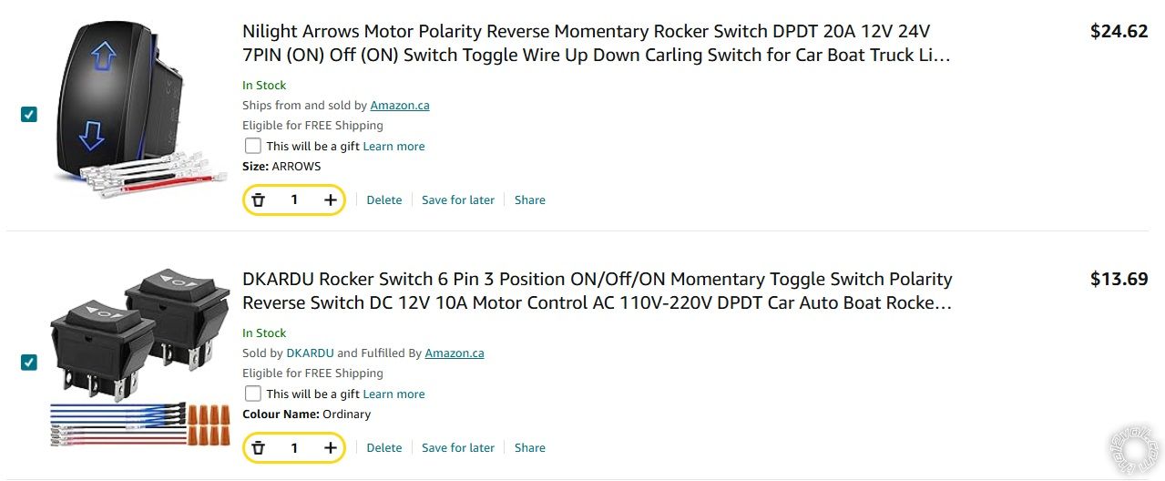
And then my good friend & fellow member gave me a wee tip, and I've run with it! Here's a sample of what I found:
Custom Electric Parking Brake Switches -- posted image.
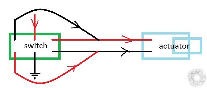
So...I hope (and expect) to find a second matching switch (SPDT?) that will provide for the activation/de-activation of both brakes. But at least I am making progress! Thanks, the12volt!
Page of 2

  Printable version Printable version Post ReplyPost New Topic
You cannot post new topics in this forum
You cannot reply to topics in this forum
You cannot delete your posts in this forum
You cannot edit your posts in this forum
You cannot create polls in this forum
You cannot vote in polls in this forum

  •  
Search the12volt.com
Follow the12volt.com Follow the12volt.com on Facebook
Wednesday, March 26, 2025 • Copyright © 1999-2025 the12volt.com, All Rights Reserved Privacy Policy & Use of Cookies
Disclaimer: *All information on this site ( the12volt.com ) is provided "as is" without any warranty of any kind, either expressed or implied, including but not limited to fitness for a particular use. Any user assumes the entire risk as to the accuracy and use of this information. Please verify all wire colors and diagrams before applying any information.

Secured by Sectigo
the12volt.com spacer
Support the12volt.com
Top
the12volt.com spacer