the12volt.com spacer
icon

How can I fix this circuit?


Post ReplyPost New Topic
< Prev Topic Next Topic >
eloshdesign 
Member - Posts: 15
Member spacespace
Joined: March 24, 2002
Location: United States
Posted: April 01, 2002 at 7:51 PM / IP Logged  
Hey the12volt,
I just wanted to say thank you very much for the diagrams! The last one worked perfect for controlling the actuators from the remote and the switch.
The only problem now is the extended pulse module did not activate the actuators on arm. The LED in the module and my test light turn on when I arm, but the actuators did nothing. Also, each time I moved the actuators down, I had to wait the 5 second delay until I could go up. No big deal for now. It's a luxury I will address later.
Thanks again!
Daren
the12volt 
Administrator - Posts: 3,957
Administrator spaceThis member has made a donation to the12volt.com. Click here for more info.spaceThis member has been recognized as an authority in Electrical Theory. Click here for more info.spaceThis member has been recognized as an authority in Mobile Audio and Video. Click here for more info.spaceThis member has been recognized as an authority in Mobile Security and Convenience. Click here for more info.spacespace
Joined: March 07, 2002
Location: Louisiana, United States
Posted: April 01, 2002 at 7:57 PM / IP Logged  

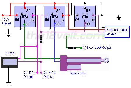
Hi Daren, do you have a positive or negative output from the extended pulse module? In my diagram, I'm assuming you have a negative output. If you have a positive output, you can simply add another relay to solve your problem.

BTW, you're welcome, glad I could help.

the12volt

eloshdesign 
Member - Posts: 15
Member spacespace
Joined: March 24, 2002
Location: United States
Posted: April 01, 2002 at 8:01 PM / IP Logged  
You're right. The test light was grounded, so it's a positive output. Any chance I could see that in picture format?
Thanks,
Daren
the12volt 
Administrator - Posts: 3,957
Administrator spaceThis member has made a donation to the12volt.com. Click here for more info.spaceThis member has been recognized as an authority in Electrical Theory. Click here for more info.spaceThis member has been recognized as an authority in Mobile Audio and Video. Click here for more info.spaceThis member has been recognized as an authority in Mobile Security and Convenience. Click here for more info.spacespace
Joined: March 07, 2002
Location: Louisiana, United States
Posted: April 01, 2002 at 9:22 PM / IP Logged  

Hi Daren, here ya go:

How can I fix this circuit? - Page 2 -- posted image.

the12volt

eloshdesign 
Member - Posts: 15
Member spacespace
Joined: March 24, 2002
Location: United States
Posted: April 02, 2002 at 9:52 AM / IP Logged  
Thanks!
Will I still have to wait for 5 seconds (extended pulse setting) after pressing down before I can go back up? If so, is there a workaround?
Daren
the12volt 
Administrator - Posts: 3,957
Administrator spaceThis member has made a donation to the12volt.com. Click here for more info.spaceThis member has been recognized as an authority in Electrical Theory. Click here for more info.spaceThis member has been recognized as an authority in Mobile Audio and Video. Click here for more info.spaceThis member has been recognized as an authority in Mobile Security and Convenience. Click here for more info.spacespace
Joined: March 07, 2002
Location: Louisiana, United States
Posted: April 02, 2002 at 9:58 AM / IP Logged  

Hi Daren, you're welcome. Please explain exactly when you get this 5 second delay and does it exist when you use the switch, door lock output, or channel 4 and/or 5?

the12volt

eloshdesign 
Member - Posts: 15
Member spacespace
Joined: March 24, 2002
Location: United States
Posted: April 02, 2002 at 10:06 AM / IP Logged  
The delay is the Extended Pulse Module's output. It is set to hold it's ouput on for about 5 seconds. This is so when I arm the alarm, the module will lower the actuators (for about 5 seconds).
I noticed when I had it hooked up the other day, I had to wait for the 5 second duration (after I moved them down) before I could push them back up. During this 5 second wait, the extended pulse module's LED was lit up. So, the ext pulse module is kinda interfering with the switch and remote operation. Does that make more sense?
the12volt 
Administrator - Posts: 3,957
Administrator spaceThis member has made a donation to the12volt.com. Click here for more info.spaceThis member has been recognized as an authority in Electrical Theory. Click here for more info.spaceThis member has been recognized as an authority in Mobile Audio and Video. Click here for more info.spaceThis member has been recognized as an authority in Mobile Security and Convenience. Click here for more info.spacespace
Joined: March 07, 2002
Location: Louisiana, United States
Posted: April 02, 2002 at 10:21 AM / IP Logged  

Hi Daren, yes, I see what's happening. The only work around would be to add another relay activated by the switch and channel 5 to interupt the extended pulse module's output to allow you to raise the actuators immediately after you've activated the module.

the12volt

eloshdesign 
Member - Posts: 15
Member spacespace
Joined: March 24, 2002
Location: United States
Posted: April 02, 2002 at 12:10 PM / IP Logged  

I hate to ask...

Diagram?
Am I a pain or what? I owe you!

Continued here: https://www.the12volt.com/installbay/display_topic_threads.asp?ForumID=1&TopicID=209&PagePosition=1

Page of 2

Sorry, you can NOT post a reply.
This topic is closed.

  Printable version Printable version Post ReplyPost New Topic
You cannot post new topics in this forum
You cannot reply to topics in this forum
You cannot delete your posts in this forum
You cannot edit your posts in this forum
You cannot create polls in this forum
You cannot vote in polls in this forum

  •  
Search the12volt.com
Follow the12volt.com Follow the12volt.com on Facebook
Tuesday, June 17, 2025 • Copyright © 1999-2025 the12volt.com, All Rights Reserved Privacy Policy & Use of Cookies
Disclaimer: *All information on this site ( the12volt.com ) is provided "as is" without any warranty of any kind, either expressed or implied, including but not limited to fitness for a particular use. Any user assumes the entire risk as to the accuracy and use of this information. Please verify all wire colors and diagrams before applying any information.

Secured by Sectigo
the12volt.com spacer
Support the12volt.com
Top
the12volt.com spacer