the12volt.com spacer
icon

Headlight Relays, Diagram Included


Post ReplyPost New Topic
< Prev Topic Next Topic >
Coomer 
Copper - Posts: 103
Copper spacespace
Joined: November 29, 2002
Location: United States
Posted: October 14, 2003 at 5:57 PM / IP Logged  
Hello,
I'm currently in the process of doing a couple things to my headlight wiring. First, I'm running new twelve gauge wires and using relays in order to upgrade my factory headlight wiring so that I can use higher-wattage headlight bulbs. Also, I'm trying to provide a reduced amount of power to my high beam bulbs when a switch is open, so that the high beams will put out some light, but won't blind people. When my high beams are on however, power to the relay providing the reduced power to the high beams will be cut, and the high beams will operate at full power. Below is a wiring diagram that I made a couple minutes ago.
Headlight Relays, Diagram Included -- posted image.
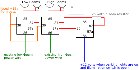
1. Will this setup do what I want it to do? I'm just not sure exactly how to provide a reduced amount of power to my high beams. I read that 25 watt, 1 ohm resistors are sometimes used in do-it-yourself DRL systems on cars, so I figured that this would work, but if you have any suggestions or comments as to why this wouldn't work or what would work better, please speak up. Headlight Relays, Diagram Included -- posted image.
2. Do I need a diode in between the high beams and the 25 watt, 1 ohm resistor, or a diode in between the high beams and terminal 87 of the middle relay?
Thanks!
Oh yeah, my high beam headlight bulbs will be running at 80 watts, if that is helpful.
xetmes 
Silver - Posts: 586
Silver spacespace
Joined: May 18, 2003
Posted: October 14, 2003 at 7:03 PM / IP Logged  

im not a big fan of using linear elements to burn off power, but it is a cheap and effective way.

i would recommend diodes on all the coils though, you dont need to isolate the 2 relays though

looks like a good idea!!

Coomer 
Copper - Posts: 103
Copper spacespace
Joined: November 29, 2002
Location: United States
Posted: October 14, 2003 at 9:15 PM / IP Logged  
When you say diodes across all of the coils, what terminals should have diodes across them? Also, which way should the diode go?
Also, do you know if the 25 watt, 1 ohm resistor will dim the high beams to about 50% of their normal brighness?
xetmes 
Silver - Posts: 586
Silver spacespace
Joined: May 18, 2003
Posted: October 15, 2003 at 5:45 PM / IP Logged  

the diodes i mean on all 3 relays cathode (band side) attached to terminal 86, anode (other side) to terminal 85.

a 1 ohm resistor will give you about 37 W or so at 13 V... i made a formula if you want to see what different values will do:

P-power output after adding resistor, Pb- power rating of bulb, V- system voltage, R- resistance of added resistor

P = ((V^4) Pb) / (V^4 + (R (Pb) )(2 V^2 + R(Pb)))

if you want to find the power disipated in the resistor use this:

P - power output from previous equation...

Pr - power disipated in resistor

R- resistance of resistor (ohms)

Pr = (P/V)^2 (R)

Coomer 
Copper - Posts: 103
Copper spacespace
Joined: November 29, 2002
Location: United States
Posted: October 15, 2003 at 6:33 PM / IP Logged  
Thank you so much for the help. I just have one more question. Should I use one resistor per high beam? Or should I use one before the wire splits to go to the high beams?
Also, I calculated the wattage that I'll get at 14 volts with 80 watts and 1 ohm of resistance, and it was just above 40.3 watts, and with the second equation, the result I got was 8.3 watts or so. Does this mean that I could get away with using a 10 watt, 1 ohm resistor?
Thanks again!
xetmes 
Silver - Posts: 586
Silver spacespace
Joined: May 18, 2003
Posted: October 15, 2003 at 6:45 PM / IP Logged  

i would use 2 resistors 25 watts each, unless they are overly expensive, it should work alright that way though. you can use the first equation for 2 lights in seires like shown just use twice the wattage (Pb) , then divide that by 2 for the wattage at each bulb, it will disipate more power and reduce the output below 50%, so i would recommend 1 - 25 watter on each

no problem with the help Headlight Relays, Diagram Included -- posted image.

Coomer 
Copper - Posts: 103
Copper spacespace
Joined: November 29, 2002
Location: United States
Posted: October 15, 2003 at 9:11 PM / IP Logged  
Alright, I think I've got it all figured out now. When I go home to pick up the car this weekend I'm going to do this modification and see how it turns out. Thanks again!

Sorry, you can NOT post a reply.
This topic is closed.

  Printable version Printable version Post ReplyPost New Topic
You cannot post new topics in this forum
You cannot reply to topics in this forum
You cannot delete your posts in this forum
You cannot edit your posts in this forum
You cannot create polls in this forum
You cannot vote in polls in this forum

  •  
Search the12volt.com
Follow the12volt.com Follow the12volt.com on Facebook
Tuesday, April 23, 2024 • Copyright © 1999-2024 the12volt.com, All Rights Reserved Privacy Policy & Use of Cookies
Disclaimer: *All information on this site ( the12volt.com ) is provided "as is" without any warranty of any kind, either expressed or implied, including but not limited to fitness for a particular use. Any user assumes the entire risk as to the accuracy and use of this information. Please verify all wire colors and diagrams before applying any information.

Secured by Sectigo
the12volt.com spacer
Support the12volt.com
Top
the12volt.com spacer