the12volt.com spacer
icon

constructing a nand gate


Post ReplyPost New Topic
< Prev Topic Next Topic >
model x 
Member - Posts: 9
Member spacespace
Joined: July 24, 2003
Location: Canada
Posted: January 22, 2004 at 7:24 PM / IP Logged  

I have a honda crx that uses two wires for the turn signals and two for the brake lights and I want to convert it to 2 wires so that the brake lights signal my turns. I know a NAND gate would do this but I don't know how to construct one or if I can construct one using relays.

What are my options? 

xetmes 
Silver - Posts: 586
Silver spacespace
Joined: May 18, 2003
Posted: January 22, 2004 at 7:46 PM / IP Logged  

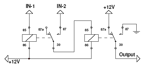
this should perform the NAND function, you may want to add diodes its your call...

constructing a nand gate -- posted image.

model x 
Member - Posts: 9
Member spacespace
Joined: July 24, 2003
Location: Canada
Posted: January 25, 2004 at 9:49 PM / IP Logged  

I don't think that'll work.  IN-1 sends a 12v signal. 

Basically this is what the truth table would look like for what I need:

X Y | output

0 0     0

0 1     Y

1 0     1

1 1     Y          

Where X is a 12v brake signal and Y is a 12v turn signal. The turn signal can also be viewed as a clock signal. 

JasonL 
Member - Posts: 20
Member spacespace
Joined: April 19, 2002
Posted: January 27, 2004 at 1:51 PM / IP Logged  
The truth table you posted describes an OR gate. The schematic posted above also implements an OR gate (not a NAND)
The truth table for a NAND gate is:
X Y    Out
0 0    1
0 1    1
1 0    1
1 1    0
Not exactly sure what you are trying to accomplish... you want the brake lights to come on when you signal a turn??? If I understand you correctly, you are going to need 3 inputs (brake, turn signal activated, and turn signal bulb) which makes the logic more complex.
xetmes 
Silver - Posts: 586
Silver spacespace
Joined: May 18, 2003
Posted: January 27, 2004 at 4:19 PM / IP Logged  

ohh man your right I drew the diagram wrong that common 12V on the coils is supposed to be ground.. ugh I dont know what I was thinking.

I dont understand your truth table what are Y outputs?

model x 
Member - Posts: 9
Member spacespace
Joined: July 24, 2003
Location: Canada
Posted: January 27, 2004 at 7:44 PM / IP Logged  

Ya when I was simplifing the logic I could use the NAND but for the circuit I need something that closely resembles an OR

XY  output

00    0

01    Y (just output whatever Y is, which would be the turnsignal)

10    1 (brake light signal)

11    Y (if I'm applying the brakes while signaling a turn I want to output the turn signal) 

Where Y is the turn signal output

hopefully this is more clear. I just want my brake lights to signal my turns.

JasonL 
Member - Posts: 20
Member spacespace
Joined: April 19, 2002
Posted: January 27, 2004 at 10:16 PM / IP Logged  
A note about truth tables... when you write output=Y, Y is already defined as an input, thus it is a fixed value. This is pure combinational logic and each set of inputs will have one and only one output. What you have written above is the same as:
X Y   Out
0 0   0
0 1   1 (because Y=1)
1 0   1
1 1   1 (because Y=1)
This will NOT accomplish what you want... because when you apply the brakes, the lights will not flash.
You will need a third logic input.
Let X = brakes applied
Let Y = turn signal activated
Let Z = turn signal bulb on (cycles between 0 and 1)
X Y Z    Out
0 0 0    0 (brakes off, turn signal off)
0 0 1    0 (brakes off, turn signal off)
0 1 0    0 (brakes off, turn signal on)
0 1 1    1 (brakes off, turn signal on)
1 0 0    1 (brakes on, turn signal off)
1 0 1    1 (brakes on, turn signal off)
1 1 0    0 (brakes on, turn signal on)
1 1 1    1 (brakes on, turn signal on)
Does that make sense?
JasonL 
Member - Posts: 20
Member spacespace
Joined: April 19, 2002
Posted: January 27, 2004 at 10:32 PM / IP Logged  
OK, being an engineer I got a little carried away with the digital logic. Whoops :D
You might be able to simply use a SPDT relay.
85 - turn signal activated (probably need to run a wire near the steering column)
86 - gnd
87a- brake switch signal
87 - turn signal (output from the flasher)
30 - brake light bulb
You would need one relay for each side, and the 85 terminal only watches for the turn signal activation for that particular side (left or right).
xetmes 
Silver - Posts: 586
Silver spacespace
Joined: May 18, 2003
Posted: January 28, 2004 at 5:26 AM / IP Logged  

K-map it constructing a nand gate -- posted image.

model x 
Member - Posts: 9
Member spacespace
Joined: July 24, 2003
Location: Canada
Posted: January 28, 2004 at 8:14 PM / IP Logged  

Alrighty,

Adding the third term makes way more sense; thanks JasonL.

And I see what you mean for the spdt relay. All I need is to find a wire that has a constant 12v when I've initiated a turn signal.

 After ploting the k-map I get

x(y)' + yz     but I this still leaves me with the task of finding the constant 12V signal that's mentioned above.

Well I can see the light now,

Page of 2

  Printable version Printable version Post ReplyPost New Topic
You cannot post new topics in this forum
You cannot reply to topics in this forum
You cannot delete your posts in this forum
You cannot edit your posts in this forum
You cannot create polls in this forum
You cannot vote in polls in this forum

  •  
Search the12volt.com
Follow the12volt.com Follow the12volt.com on Facebook
Thursday, April 18, 2024 • Copyright © 1999-2024 the12volt.com, All Rights Reserved Privacy Policy & Use of Cookies
Disclaimer: *All information on this site ( the12volt.com ) is provided "as is" without any warranty of any kind, either expressed or implied, including but not limited to fitness for a particular use. Any user assumes the entire risk as to the accuracy and use of this information. Please verify all wire colors and diagrams before applying any information.

Secured by Sectigo
the12volt.com spacer
Support the12volt.com
Top
the12volt.com spacer