the12volt.com spacer
icon

Please help install car alarm system


Post ReplyPost New Topic
< Prev Topic Next Topic >
snoopy123 
Member - Posts: 8
Member spacespace
Joined: November 16, 2004
Location: United States
Posted: November 18, 2004 at 9:41 PM / IP Logged  

Halo,,,this is the first I want to try to install a system by myself.  It is a keyless entry, remote starter and alarm combo system.  I bought it from ebay, and it only came with operation manual and wire diagram.  I have no idea where should connect to for most wires.  Please help me.  Thank you in advances.

Please tell me where should I connect wires to which wires from car by color and number.  Thank you very much.

WIRING INFORMATION 1999 Hyundai Elantra

NUMBER, WIRE, WIRE COLOR, LOCATION

1, 12V CONSTANT WIRE, BLUE/RED, Ignition harness

2, 12V IGNITION WIRE, BLACK/ WHITE, Ignition harness

3, SECOND IGNITION WIRE, BLUE / YELLOW, Ignition harness

4, 12V ACCESSORY WIRE, BLUE/BLACK, Ignition harness

5, STARTER WIRE, BLACK / YELLOW, Ignition harness

6, PARKING LIGHTS (+), GREEN / WHITE, Harness In Driver’s Kick Panel

7, DOOR TRIGGER/ DOMELIGHT SUPERVISION (-), BLACK/ RED, At Any Door Pin

8, TRUNK TRIGGER (-), BLUE / YELLOW or BROWN / RED, At Light In Trunk

9, TACHOMETER WIRE, BROWN / RED or BLUE / YELLOW, At Ignition Coil

10, BRAKE WIRE (+), GREEN Harness, At Brake Pedal Switch

11, HORN TRIGGER (-), BLACK/ WHITE Harness, At Steering Column

12, LEFT FRONT WINDOW UP, BLUE/WHITE, At Driver Window Motor Inside Door

13, LEFT FRONT WINDOW DOWN, BROWN, At Driver Window Motor Inside Door

14, RIGHT FRONT WINDOW UP LT, BLUE, Harness In Driver’s Kick From Driver Door

15, RIGHT FRONT WINDOW DOWN, PINK, Harness In Driver’s Kick From Driver Door

16, LEFT REAR WINDOW UP, WHITE, Harness In Driver’s Kick From Driver Door

17, LEFT REAR WINDOW DOWN, RED / BLACK, Harness In Driver’s Kick From Driver Door

18, RIGHT REAR WINDOW UP, YELLOW, Harness In Driver’s Kick From Driver Door

19, RIGHT REAR WINDOW DOWN, GREEN/ BLACK, Harness In Driver’s Kick From Driver Door

jrilla 
Gold - Posts: 1,498
Gold spaceThis member has made a donation to the12volt.com. Click here for more info.spacespace
Joined: November 19, 2002
Location: North Dakota, United States
Posted: November 18, 2004 at 10:15 PM / IP Logged  
Hows abouts this: You post the alarm diagram and then tell us what part about it you dont understand.
The list of wires you posted is almost all you need. The diagram you have should refer to most of those wires then you just need to get into some dirty ass clothes get a old sofa cushion and kneel down and start looking for wires with a volt meter. If you dont know how to test to make sure you have found the right wire just ask. 12v+ constant means just what it says. 12v+ Ignition is 12v+ in ON and Crank position. Acc drops out during cranking just like you blower and radio do when you start the car with a key. And so on and so forth.
J Rilla
Owner/Installer
Velocity Motors 
Moderator - Posts: 12,488
Moderator spaceThis member has made a donation to the12volt.com. Click here for more info.spaceThis member has been recognized as an authority in Electrical Theory. Click here for more info.spaceThis member has been recognized as an authority in Fabrication. Click here for more info.spaceThis member has been recognized as an authority in Mobile Audio and Video. Click here for more info.spaceThis member has been recognized as an authority in Mobile Security and Convenience. Click here for more info.spacespace
Joined: March 08, 2002
Location: Manitoba, Canada
Posted: November 18, 2004 at 10:17 PM / IP Logged  
Have you ever held a wire stripper or a soldering iron before ? I ask because if you have not and so not know how to operate a DMM, I suggest that you spend the money to have it installed properly instead of running the risk of damaging expensive components on the vehicle.
Jeff
Velocity Custom Home Theater
Mobile Audio/Video Specialist
Morden, Manitoba CANADA
snoopy123 
Member - Posts: 8
Member spacespace
Joined: November 16, 2004
Location: United States
Posted: November 19, 2004 at 5:47 PM / IP Logged  

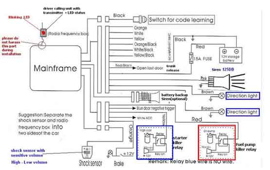
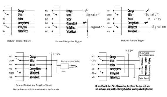
O,,,I don't know why yahoo took off the alarm diagrams.  Here, I post them again.

I have wire stripper and screwdriver.  I will go to buy some vinyl electrical tape, crimps, and a digital Multi-meter.  Is that all I need?  (1) I don't know where should I connect wires (orange to yellow/black) to?  (2) where can I find battery ground?  (3) for the black wire, I should connect to ground then to (-) terminal? (4) where is direction light? (5) how to connect fuel pump killer relay and starter killer relay? (6) where is blue door negative trigger and white ACC?  Thank you very much. 

Please help install car alarm system -- posted image.

Please help install car alarm system -- posted image.

snoopy123 
Member - Posts: 8
Member spacespace
Joined: November 16, 2004
Location: United States
Posted: November 19, 2004 at 5:51 PM / IP Logged  

Hope yahoo won't take them off again.

Please help install car alarm system -- posted image.Please help install car alarm system -- posted image.

silversi17 
Member - Posts: 25
Member spacespace
Joined: December 31, 2003
Location: United States
Posted: November 19, 2004 at 11:50 PM / IP Logged  

My first piece of advice to you is not to crimp anything, all connections should be soldered.

Second, I'm all for learning by doing, but if you don't even know where to get ground, I would seriously consider having someone who knows what they are doing help you out on this one.

lesserblue 
Member - Posts: 18
Member spacespace
Joined: October 30, 2004
Posted: November 20, 2004 at 1:46 AM / IP Logged  
The questions you're asking are extremely basic and makes this a little scary.
***Disclaimer*** If you've never used a soldering iron or installed an alarm you might be biting off a little more than you can chew with this one. If you have a friend who has done it, ask them for help or to lend a hand.
Before you start, please spend at least a week (several hours a day) reading the information available on this site...
Starting Here
1. Orange, white, yellow, ORANGE / black, WHITE/ black, yellow/black are for door locks.
      Click here for info about determining your type of locks.
2. Battery/Chassis ground can be obtained any where on the car.
3. Just connect to the chassis somewhere (unpainted area).
4. Direction lights are your parking lights.
    Connect this to #6, PARKING LIGHTS (+), GREEN / WHITE, Harness In Driver’s Kick Panel
5. Starter Kill/Interrupt
The Fuel Interrupt would look alot like the starter interrupt but would cut the power to the fuel pump.
6. Connect "Blue door negative trigger" to #7, DOOR TRIGGER/ DOMELIGHT SUPERVISION (-), BLACK/ RED, At Any Door Pin
    connect "white acc" to #4, 12V ACCESSORY WIRE, BLUE/BLACK, Ignition harness
I highly recommend you read the following...
Resistors
Relays
Ohm's Law
Diodes
Converting Polarity with Relays
Educate yourself first, then have fun but be careful.
BTW, If you have airbags, don't touch any big yellow wires! They could be for the Airbags and cause the to deploy.
I love the part where it says, "Please do not harass this part during installation."Please help install car alarm system -- posted image.
StanCamacho 
Member - Posts: 5
Member spacespace
Joined: November 21, 2004
Location: Canada
Posted: November 21, 2004 at 10:13 PM / IP Logged  

Hi I have almost same alarm starter combo the model is al838s the manual it's almost useless my problem is everytime press the foot brek it tries to lock my doors so the doors lock when I start the car then I'm driving I try to slowdown and click, try to stop and click any time I press the brek click it's a pain to hear the doors clicking all the time I use the foot brek. My other problem is the remote starter I remote start the car and a couple seconds later I hear the noise the starter trywing to crank again, I used the purple wire from the alrm/starter  unit and connected to a white wire inside the car on passenger side on harness that comes from the front of the car assuming that is the tach wire I start the car and test with a meter and the signal is 0V to 1.3V on idle when I press the gas pedal the signal goes up any help would be great.

Stan Camacho
StanCamacho 
Member - Posts: 5
Member spacespace
Joined: November 21, 2004
Location: Canada
Posted: November 21, 2004 at 10:18 PM / IP Logged  

Hi I have almost same alarm starter combo the model is al838s the manual it's almost useless my problem is everytime press the foot brek it tries to lock my doors so the doors lock when I start the car then I'm driving I try to slowdown and click, try to stop and click any time I press the brek click it's a pain to hear the doors clicking all the time I use the foot brek. My other problem is the remote starter I remote start the car and a couple seconds later I hear the noise the starter trywing to crank again, I used the purple wire from the alrm/starter  unit and connected to a white wire inside the car on passenger side on harness that comes from the front of the car assuming that is the tach wire I start the car and test with a meter and the signal is 0V to 1.3V on idle when I press the gas pedal the signal goes up any help would be great.

My car is 1996 Firebird convertable 3.8L V6 I made a module to bypass the antithef, starer killer, I used streat connection to door locks using 2 diodes one for door triger to waikup the RAP module and one door lock I connected the trunk release without relay on the positive wire after the factory relay

Stan Camacho

Sorry, you can NOT post a reply.
This topic is closed.

  Printable version Printable version Post ReplyPost New Topic
You cannot post new topics in this forum
You cannot reply to topics in this forum
You cannot delete your posts in this forum
You cannot edit your posts in this forum
You cannot create polls in this forum
You cannot vote in polls in this forum

  •  
Search the12volt.com
Follow the12volt.com Follow the12volt.com on Facebook
Thursday, April 18, 2024 • Copyright © 1999-2024 the12volt.com, All Rights Reserved Privacy Policy & Use of Cookies
Disclaimer: *All information on this site ( the12volt.com ) is provided "as is" without any warranty of any kind, either expressed or implied, including but not limited to fitness for a particular use. Any user assumes the entire risk as to the accuracy and use of this information. Please verify all wire colors and diagrams before applying any information.

Secured by Sectigo
the12volt.com spacer
Support the12volt.com
Top
the12volt.com spacer