the12volt.com spacer
icon

2001 Nissan Frontier, Autopage RS855


Post ReplyPost New Topic
< Prev Topic Next Topic >
metaverse 
Copper - Posts: 210
Copper spacespace
Joined: June 13, 2002
Location: United States
Posted: January 23, 2005 at 8:02 PM / IP Logged  
Reverse the polarity of the relay to give a negative signal. Connect 87 to ground and the output on 30 should be a negative..
radkonn 
Copper - Posts: 73
Copper spacespace
Joined: January 21, 2005
Posted: January 25, 2005 at 11:24 PM / IP Logged  
Does anybody have a tech sheet for a 2001 Nissan Frontier that shows the location/wire color driver's door unlock motor wire, and the door triggers for driver, passenger, and rear doors.
radkonn 
Copper - Posts: 73
Copper spacespace
Joined: January 21, 2005
Posted: January 25, 2005 at 11:29 PM / IP Logged  
Metaverse
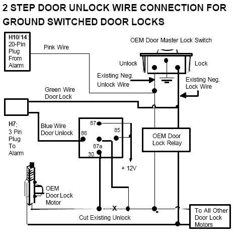
When you wire up this alarm for double pulse unlock, does the alarm send the pulse to H10/14(pink) first or to the H7 blue wire? I'm looking at page 17 diagram, 2 STEP UNLOCK WIRE CONNECTION FOR GROUND SWITCHED DOOR LOCKS.
Thanks
TJ92Civic 
Copper - Posts: 161
Copper spacespace
Joined: November 13, 2004
Location: United States
Posted: January 26, 2005 at 12:04 AM / IP Logged  
2001 Nissan Frontier

ItemWire ColorPolarityWire Location
12Vgreen+ignition harness
STARTERBLACK / YELLOW+ignition harness
IGNITIONBLACK/ white+ignition harness
ACCESSORYRED / yellow+ignition harness
SECOND ACCESSORYnone
TACHOMETERpink/blue or blackinstrument cluster or ECM *2
POWER LOCKyellow *7-*3
POWER UNLOCKyellow/red *7-*3
PARKING LIGHTS +blue/redsteering column
PARKING LIGHTS -none
DOOR TRIGGERRED / black *4-*3
HEADLIGHTSred, RED / blk *5+steering column
WIPERS*6-steering column
LF WINDOW UP/DNblue - blu/blkAat drivers door switch
RF WINDOW UP/DNblu/yel - blu/whtAat drivers door switch
LR WINDOW UP/DNnone
RR WINDOW UP/DNnone
TRUNK/HATCH PINnone
HOOD PINBLACK/ pink-*3
TRUNK/HATCH RELEASEnone
FACTORY ALARM ARMarms with lock
FACTORY ALARM DISARMdisarms with unlock
HORN TRIGGERlt grn/red or brown-steering column
BRAKE WIREBROWN / red+brake pedal switch
LOCK MOTORblue*3
UNLOCK MOTORGREEN / WHITE*3
DISARM DEFEATpurple or blu/red *9*3
DISARM NO UNLOCK*8
DOME SUPERVISIONnonenonnone
SPEED SENSEdk. GREEN/ black2ECM *2
SUN ROOF OPEN/CLOSEnonenonnone
SUN ROOF LIMITnonenonnone
LF SPEAKERnonenonnone
RF SPEAKERnonenonnone
LR SPEAKERnonenonnone
RR SPEAKERnonenonnone
RADIO 12Vnonenonnone
RADIO GROUNDnonenonnone
RADIO SWITCHnonenonnone
RADIO ILLUMINATEnonenonnone
POWER ANTENNAnonenonnone
 
Notes:*1 Not required for remote start. *2 The ECM is located below the heater box to the right of the accelerator pedal, behind trim panel. The tach is in the top row, 3rd pin left of center of the plug. The VSS is in the 2nd row from the top, 4th pin right of center. *3 Located at the Smart Entrance Control Unit above the hood release in the drivers kick panel. The door lock wires only meter when turn the key in either door key cylinder. *4 If equipped with factory dome light delay, use GREEN/ red(-) for the drivers door and GREEN/ black(-) for the passenger door. Diode isolate each wire. The RED / black may also be found in the drivers A pillar. *5 These wires are for the low beams. For the high beams use RED / green(+) and RED / white(+) at the same location. *6 Use WHITE/ blue for intermittent, WHITE/ red for low, and blue/white high. *7 Unlock requires a double pulse. On vehicles without the factory alarm, can also find lt. GREEN/ red for lock and brown for unlock. *8 A single pulse to the unlock wire will disarm the factory alarm without unlocking the doors. *9 It is purple on the 2 door models, and blue/red on the 4 door.

metaverse 
Copper - Posts: 210
Copper spacespace
Joined: June 13, 2002
Location: United States
Posted: January 26, 2005 at 1:08 PM / IP Logged  
Look at the diagram on page 18..it includes use of the pink wire. The pink wire should give a double pulse unlock along with the blue. Maybe you meant page 18 instead of 17..my electronic PDF of RS-855 install manual has it on page 18.
Look at the setting on page 21 alarm feature B programming..set it to double pulse. Also look at the Alarm feature C programming on page 21 Tell it the pink wire is to be used for two step unlock output. I understand it is the default setting, but, go verify it nonetheless.
There is a way to to tap into the door lock timers on nissan's to use the priority unlock that the factory remote fob's use..Unfortunately, I don't know that circuitry..blah..would come handy on both of my nissans...lol.
radkonn 
Copper - Posts: 73
Copper spacespace
Joined: January 21, 2005
Posted: January 26, 2005 at 11:30 PM / IP Logged  
I figured out which wire controls the central lock, but I am confused about which wire is for the door lock motor. There are two GREEN / WHITE wires at the SECU. One is a heavier gauge wire than the other. Is the door lock wire usually a heavier guage? How do I test the wire to see if it is the right one? All the tech sheets say to test it with the key cylinder. What does that mean?
metaverse 
Copper - Posts: 210
Copper spacespace
Joined: June 13, 2002
Location: United States
Posted: January 27, 2005 at 10:30 PM / IP Logged  
Take a look at this link: Lock tips
radkonn 
Copper - Posts: 73
Copper spacespace
Joined: January 21, 2005
Posted: January 28, 2005 at 12:29 AM / IP Logged  
I found the wire. It was the heavier gauge wire out of the two. I tested it and only the driver's door locked. I'm finished with the alarm, but I haven't started to program it yet. Anything I should know about the process, or is it straight forward?
radkonn 
Copper - Posts: 73
Copper spacespace
Joined: January 21, 2005
Posted: January 28, 2005 at 6:05 PM / IP Logged  
I got everything working, almost. The remote start works great. This isn't a bad alarm at all. I cut the driver's door lock motor wire and applied 12volts to the motor side, and it just unlocked the driver's door like it should. However, when I press the unlock button on the transmitter, it unlocks both doors. I couldn't find the yellow and yellow/red wires at the secu, so I used the alternate wire colors that were on my tech sheet for vehicles without factory alarms. I tested this wire with and a single pulse would unlock all doors. How are alarms usually set up when programmed for double pulse? There is two unlock wires coming from the brain. One wire goes to the relay hooked up to the door lock motor, and the other goes to the central door switch. Does the brain send a single negative pulse to both wires with one press of the transmitter and another pulse to the main switch upon the second press?
Also, I went into test mode and tried to adjust the shock sensor, but I can only get the first warning out of it. It is supposed to be a 2 stage shock sensor, but I am only getting a warning and not full alarm in test mode or out. I even set the sensitivity high and tapped on the shock sensor, still no luck. Any ideas?
metaverse 
Copper - Posts: 210
Copper spacespace
Joined: June 13, 2002
Location: United States
Posted: January 29, 2005 at 11:08 AM / IP Logged  
I don't think test mode will do a full trigger..it is just to verify if the sensor is even working and to adjust warning..
As for the lock..you got me. If you wired it up as the picture below, it should work..
2001 Nissan Frontier, Autopage RS855 - Page 2 -- posted image.
Page of 3

  Printable version Printable version Post ReplyPost New Topic
You cannot post new topics in this forum
You cannot reply to topics in this forum
You cannot delete your posts in this forum
You cannot edit your posts in this forum
You cannot create polls in this forum
You cannot vote in polls in this forum

  •  
Search the12volt.com
Follow the12volt.com Follow the12volt.com on Facebook
Tuesday, April 23, 2024 • Copyright © 1999-2024 the12volt.com, All Rights Reserved Privacy Policy & Use of Cookies
Disclaimer: *All information on this site ( the12volt.com ) is provided "as is" without any warranty of any kind, either expressed or implied, including but not limited to fitness for a particular use. Any user assumes the entire risk as to the accuracy and use of this information. Please verify all wire colors and diagrams before applying any information.

Secured by Sectigo
the12volt.com spacer
Support the12volt.com
Top
the12volt.com spacer