the12volt.com spacer
icon

Integrating garage opener


Post ReplyPost New Topic
< Prev Topic Next Topic >
D'Ecosse 
Copper - Posts: 49
Copper spacespace
Joined: October 24, 2004
Posted: February 23, 2006 at 12:00 PM / IP Logged  

dualsport wrote:
...If it came down to needing that extra draw, I'd stick with the original battery power, especially since it's used only intermittently.

Interesting logic - use a couple of AA batteries will will obviously have considerable lifetime and spare the (what - 65Ah?) car battery from the 'significant' (sic!) power draw?   Integrating garage opener - Page 3 -- posted image.

I know you're trying to make a point here but its just not a realistic concern - sure, anything that is connected to a battery that is sinking current, regardless of how small, will ultimately drain the stored energy. But that is not unique to this device & in this case the draw is certainly small enough that it is not going to drain the battery even over a couple of weeks. We're talking about a very small current, not a 5W light bulb here!

Guys who are building Led tails are using multiple regulators and there is no general concern for alarming excessive drain problems. You're just just over-stating the issue and creating needless trepidation.

Anyone who is parking their car for extended periods without running should seriously consider a trickle charger anyway. I prefer the Battery Tender model myself and have a permanent connection to the battery with an extender pigtail connector in the front bumper that I can reach and connect to without even popping the hood.

See it here - click 

iceohio 
Member - Posts: 37
Member spacespace
Joined: November 26, 2005
Location: United States
Posted: February 23, 2006 at 12:28 PM / IP Logged  

I'd considered just jumpering the switch permanently and using the relay to add power to the circuit to turn it on/off... But the problem I could foresee is the remote losing it's memory or whatever if it sat powered off for too long.  It's a Security+ unit.

Maybe someday I'll add a little solar power cell somewhere to trickle charge the battery in case it's parked a long time.  If it were to go dead sitting a few weeks, I can live with that, or buy a better battery or something.  I'm going to go to RS later and buy the stuff to build it as in the diagram.  I may even add another dash mounted female plug for plugging in my PDA and cell on long trips.  Who knows?

You guys have opened a lot of doors!  Thanks!

dualsport 
Silver - Posts: 983
Silver spacespace
Joined: September 27, 2005
Location: United States
Posted: February 23, 2006 at 2:01 PM / IP Logged  
D'Ecosse wrote:

Interesting logic - use a couple of AA batteries will will obviously have considerable lifetime and spare the (what - 65Ah?) car battery from the 'significant' (sic!) power draw?   Integrating garage opener - Page 3 -- posted image.

I guess you consider a constant draw of the regulator circuit the same as the case where the battery is open circuited until the remote is actually in operation.  If so, that's even more interesting logic- 

sic-

If the inefficiency doesn't bother you, it's fine.

iceohio 
Member - Posts: 37
Member spacespace
Joined: November 26, 2005
Location: United States
Posted: February 23, 2006 at 2:23 PM / IP Logged  

I didn't mean to start a war here hehehe.

Given the relatively low cost to make these.. I'll make one both ways.  I need to make two more anyway.  The Camry has an awesome battery, so I'll use the one in the diagram for that one.  For the Honda, I'll use the lower discharge one.  Heck, I may even try breadboarding one without a battery... I'll rig it so the relay closes the circuit and powers the remote.  Using the power as the on/off. 

I have a gut feeling doing that will cut into the life expectancy of the remote though (even if memory is not an issue).  I used to have a heater that the switch went bad on.  I just wired it to permanently on and put a switch on the power cord.  It worked fine but burnt out after a couple months.  Someone told me that it was probably spikes due to it getting power and instantly turning on.  Capacitors not having time to charge or something... I'm no electrical genius.. Just a hack ;-)

Being 3V and DC I don't think that capacitance is an issue or anything... Just the potential spike scares me.

If this way worked, it would certainly be the best way.  Then there's no power drain at all when at rest.

Joseph

iceohio 
Member - Posts: 37
Member spacespace
Joined: November 26, 2005
Location: United States
Posted: February 24, 2006 at 1:17 PM / IP Logged  

Perhaps I missed something...

I went out and bought the LM317, a 1/2W 330 ohm resistor, a 220 and two 10 ohm resistors, a board, and good solder.

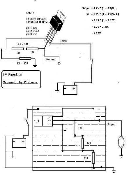
I wired it as the diagram indicates, only variation being I put the three resistors in series (to total 240 ohms). 

I found an AC to 12VDC transformer to use as a test.  I cut the ends off, made sure the polarity was correct, and connected it up.  My output was around 9 volts.  ???

I thought I may have connected the LM317 backwards, but reversing it gave me a full 12V.

I did some reviewing, and the resistors in series shouldn't be the problem.  I tested the resistance across them and they can out to be about 242 ohms (within varience).  Did I do something wrong?

D'Ecosse 
Copper - Posts: 49
Copper spacespace
Joined: October 24, 2004
Posted: February 24, 2006 at 1:52 PM / IP Logged  

Integrating garage opener - Page 3 -- posted image.

Make sure you have everything connected up properly. See above for suggested layout

Recognize that the heatsink is connected to pin 2 so be sure that it not touching anything else!

(Replace the 2 x 120's with your string of 220 & 2 x 10's)

iceohio 
Member - Posts: 37
Member spacespace
Joined: November 26, 2005
Location: United States
Posted: February 24, 2006 at 2:12 PM / IP Logged  

It works!

I had it wired incorrectly.  Your picture really helped!  If you're ever around Columbus, Ohio, the beer is on me!

D'Ecosse 
Copper - Posts: 49
Copper spacespace
Joined: October 24, 2004
Posted: February 24, 2006 at 2:19 PM / IP Logged  

Congratulations! Integrating garage opener - Page 3 -- posted image.  Integrating garage opener - Page 3 -- posted image.

Have fun with the next part, integrating into your GDO transmitter.

iceohio 
Member - Posts: 37
Member spacespace
Joined: November 26, 2005
Location: United States
Posted: February 24, 2006 at 2:29 PM / IP Logged  

Thanks!

I let it sit powered up for a few minutes to check the heat.  Resistors are cold (good) the 317 is a bit warm, but nothing to be concerned about.

The voltage dropped to about 2V though.  Could be my very poor wiring causing it.  I'll rerig it later with solder instead of twisted wires, and check again.  I have no doubt it'll be fine :)  Thanks again!

Joseph

D'Ecosse 
Copper - Posts: 49
Copper spacespace
Joined: October 24, 2004
Posted: February 24, 2006 at 2:36 PM / IP Logged  
If you want to optimize the heat transfer from the LM317T you can always use one of these
Page of 4

  Printable version Printable version Post ReplyPost New Topic
You cannot post new topics in this forum
You cannot reply to topics in this forum
You cannot delete your posts in this forum
You cannot edit your posts in this forum
You cannot create polls in this forum
You cannot vote in polls in this forum

  •  
Search the12volt.com
Follow the12volt.com Follow the12volt.com on Facebook
Thursday, May 2, 2024 • Copyright © 1999-2024 the12volt.com, All Rights Reserved Privacy Policy & Use of Cookies
Disclaimer: *All information on this site ( the12volt.com ) is provided "as is" without any warranty of any kind, either expressed or implied, including but not limited to fitness for a particular use. Any user assumes the entire risk as to the accuracy and use of this information. Please verify all wire colors and diagrams before applying any information.

Secured by Sectigo
the12volt.com spacer
Support the12volt.com
Top
the12volt.com spacer