the12volt.com spacer
icon

Properly fused and wired?


Post ReplyPost New Topic
< Prev Topic Next Topic >
conti2k 
Member - Posts: 12
Member spacespace
Joined: October 06, 2005
Location: United States
Posted: March 08, 2006 at 2:31 PM / IP Logged  
Hi folks -
just put together a quick diagram to work from when wiring this all up. Just wanted to get some input on whether this is laid out correctly etc. *before* I work on it.
Properly fused and wired? -- posted image.
The numbers should all be in there, though if there are any questions, let me know... the lines from the battery to the first distribution block are 1/0ga and all wires past that are 4ga. From the battery to the distribution block is about 15ft, after that from the distribution block to the amps is less than 2ft.
Also the cap is a hybrid battery/capacitor setup that I'm planning to just run the Sub-amp off of. The instructions with it said to ground to the battery. I figured since I'm already grounding one amp to the battery, might as well ground both to the battery? Or is my logic flawed there?
Thanks for any insights!
C2K
.: Conti2k :.
2000 Lincoln Continental
Alpine CDA-9855 with stock speakers & sub
Soundstream gear coming soon
mad550 
Copper - Posts: 201
Copper spacespace
Joined: February 23, 2006
Location: Australia
Posted: March 08, 2006 at 2:54 PM / IP Logged  
Looks ok to me should work just fine,  just make sure your grounds are clean etc and you shouldn't have any problems.
WOW Sight and Sound
Maroochydore
Nothing is impossible!
Do it right the first time or don't do it at all.
jeffchilcott 
Platinum - Posts: 2,483
Platinum spacespace
Joined: April 11, 2002
Location: United States
Posted: March 08, 2006 at 3:25 PM / IP Logged  
you should ground withen 3 ft of your amps, not back to the battery terminal...I have heard of some people doing this with alright results, but would recomend using a chasis ground withen 3 ft of the amps.     Also a cap is meant to be wired in-line to your amp
I.E   BAT+-----CAP+-----AMP+
then ground the cap to the chasis.
Also caps are typically useless but with the amount of current draw you will have, this might just be acceptible.    What type of vehicle is this going into, and have you upgraded the BIG 3?
If not look at the sticky post on the "BIG 3" at the top of the fourm
2009 0-1000 Trunk WR 154.0DB 2009 1001+ Trunk WR
2007 USACI World Champion
2007 World Record
2006 USACI Finals 2nd Place
Teslank 
Member - Posts: 29
Member spacespace
Joined: May 14, 2004
Location: Canada
Posted: March 08, 2006 at 3:51 PM / IP Logged  

you can wire the cap like in the diagram it is not important to get in line with the power lines...

because the cap acts like a container under pressure of 14.4volts(ex.) if the alternator goes below that for 1milli second it will deliver its pressure.

and if you want to have a cap to compensate for voltage drops when hitting bass goes loud you need at least a 20 farad cap. why? charge up your cap, disconnect, and put a test light on it. how much time will it light? not even a second. so think about the amp taking 80amps. a test light take 1to4 amps max!

i learned this in applicated electricity at my mechanic school...

tell me if i am terribly wrong but i asked these kind of question to my proffesor in the past.

another thing that is ridiculous to me the ground wire "3 ft max to ground". wtf if you talk about conventional electricity;; power flow from + to -.

but this is not reality. reality flow is - to +. and we all know that all our power setups on the + side is at least 13 ft long!

i heard alot of things and it is ridiculous.

Set-up:
Car: Toyota Corolla 1997
Head-unit: Alpine 9815
Amp: Lightning Audio STORM X1.800.4
Sub: Lightning Audio STRIKE S4.12.4
Front SPK: Phoenix Gold OCTANE-R 6.5 comp.
Rear SPK: Pionneer 6X9
conti2k 
Member - Posts: 12
Member spacespace
Joined: October 06, 2005
Location: United States
Posted: March 08, 2006 at 4:00 PM / IP Logged  
Thanks for the replies.
Jeff - the cap is not a 'true' cap - it's basically a battery with extremely rapid charge and discharge capabilities. The manufacturer recommends wiring it in parallel to the regular battery. To quote from their info:
It "should be wired in parallel to your existing battery, as close to your amplifiers as possible, using heavy gauge cable. Do not ground to the frame."
The diagram that was included with it indicated that the best way to wire it was to run a power line and ground just like in the diagram I included earlier, with the only alternative option being grounding just the cap to the battery and grounding the amp to the body of the car.
The car this is going into is a model year 2000 Lincoln Continental. The "Big 3" is also (being) taken care of. I just put in an Optima red top battery, and have a new custom built 250amp alternator waiting to replace the stock 130amp one, once I finish the install with a friend of mine. It's all being wired up with 1/0ga wire (between the battery, alternator, etc.)
.: Conti2k :.
2000 Lincoln Continental
Alpine CDA-9855 with stock speakers & sub
Soundstream gear coming soon
mad550 
Copper - Posts: 201
Copper spacespace
Joined: February 23, 2006
Location: Australia
Posted: March 08, 2006 at 4:32 PM / IP Logged  
we don't have to worry about altenators in Australia as they come factory 120A output he he he
WOW Sight and Sound
Maroochydore
Nothing is impossible!
Do it right the first time or don't do it at all.
forbidden 
Platinum - Posts: 5,352
Platinum spaceThis member has made a donation to the12volt.com. Click here for more info.spaceThis member has been recognized as an authority in Mobile Audio and Video. Click here for more info.spacespace
Joined: November 01, 2003
Location: Alberta, Canada
Posted: March 08, 2006 at 5:08 PM / IP Logged  
Read the grounding sticky as to what a proper ground is. If after you measure the return resistance reading and it is low enough, then you will not need to ground to the front battery. Personally, I would and I would use a 0 gauge line from the front to the back for both. It might be a little overkill, but I would still have another fuse on the power line to the second rear battery. There is no need for the fused distro blocks as the amps have built in internal fuses, save that couple of $ and use matching distro blocks. You can also eliminate the second set of distro blocks by running the second battery direct to the main distro blocks as well, nothing wrong with this at all. Current flows so fast that an extra 3 feet of wire will make no difference at all.
Top Secret, I can tell you but then my wife will kill me.
conti2k 
Member - Posts: 12
Member spacespace
Joined: October 06, 2005
Location: United States
Posted: March 08, 2006 at 5:09 PM / IP Logged  
well, stock on this car is 130A... which is nowhere near enough to run this setup without risk of blowing or melting the alternator... hence the 250A replacement...
.: Conti2k :.
2000 Lincoln Continental
Alpine CDA-9855 with stock speakers & sub
Soundstream gear coming soon
conti2k 
Member - Posts: 12
Member spacespace
Joined: October 06, 2005
Location: United States
Posted: March 09, 2006 at 12:38 AM / IP Logged  
Thanks much for the insights. So, I have two "T" distribution blocks that have 1 input for 1/0ga and 3 for 4ga so that'll be perfect, with two lines going to the amps and one to the cap for both the power and ground... makes the wiring a lot less complicated too.
As far as fuses goes, since one amp has two 30a fuses, and the other has three 30a fuses, am I correct in assuming I can put a single 150a fuse on the power line from the main battery to have proper coverage? Or should I aim a little lower (like 125)?
Thanks!
.: Conti2k :.
2000 Lincoln Continental
Alpine CDA-9855 with stock speakers & sub
Soundstream gear coming soon
stevdart 
Platinum - Posts: 5,816
Platinum spaceThis member has made a donation to the12volt.com. Click here for more info.spaceThis member has been recognized as an authority in Mobile Audio and Video. Click here for more info.spaceThis member consistently provides reliable informationspace
Joined: January 24, 2004
Location: Pennsylvania, United States
Posted: March 09, 2006 at 8:19 AM / IP Logged  

The idea of fusing the main power wire is to protect the car from fire if the wire should be damaged and short out.  Fusing for any power wire should be to the capacity of the wire, not to the capacity of the appliances connected downstream.  With a 250 amp alt, it's your choice whether to use 2 ga. or 1/0 for your sound system.  If you use 2 ga., fuse the main wire at the source (the batt. under the hood) with a 225 amp fuse or breaker.  See Power and Ground Cable Specs.

You should use 1/0 for the Big 3 upgrades due to the fact that 2 ga. is a lower capacity than the alt outputs.  But wiring from the batt. to the sound system could be 2 ga. and give it plenty of current-carrying capacity.  That's up to you which to use for the run from engine to trunk, but if you use a 1/0 for this you should still follow the guidelines of fusing wires, with this exception:  if the power supply is no more than 250 amps, you can fuse the 1/0 wire to that rating instead of going up to 350 amps.

Let's look at some other things.  A cap will only discharge to an amplifier if the amplifier demands it.  You don't need to separate the 2nd batt/cap from the 4 channel amp...if that amp doesn't demand the boost it will not be a factor.  This is to say, you should simplify the install by wiring as a "2 battery" system, with the batt/cap as your second battery connected in parallel with the main battery.  All system components are connected to the second battery, which is in their vicinity.  Since you are wiring its ground directly to the main battery, the ground on the 2nd batt will be your grounding point for all components...the chassis will not be the ground return.  (Actually, your pic shows all parallel wiring, which is an instant connection at all points.  Even though you show a separation of components and have it arranged as such, they are all instantly connected.  The four channel amp is thus connected to the batt/cap in your depiction just as much as the mono amp is.)  And you need more fuses in the scheme because you have a second battery involved.

Fusing:  If it weren't for the sake of safety there would be no use for fuses whatsoever.  With safety in mind, when a power wire is downsized at any point, the lesser ga. wire needs its own protective fuse.  The fuse is placed at the source end of the wire.  The closest place on that wire to the source (battery) is the junction where it branched off of the main wire.  So when you have a large main power wire split to feed multiple amps, the wires to those amps need to be fused at the point of distribution. 

As you follow the path further downstream, the amplifier fuses the incoming current at the source side as well.  The amp's fuse protects the amp, not the wire that feeds it.  So if you are using 4 ga. wires to the individual amps, each wire should be fused with a 150 amp fuse.  (Fuse ratings are typically lowered closer to the capacity of the appliance than to the capacity of the wire in these situations, but they remain higher than the appliance values but not higher than the wire capacity.)

Here's a schematic for what I described.  The fuses on the smaller wires feeding the amps are a diagram of a fused distro block.  The power and ground wires exiting the second battery are the same ga. as the main wires connecting the batteries (because they are a continuation from the power source), and the fuses at the 2nd batt are rated per the wire gauge, as is the fuse at the main battery.  Regardless of how the wires are run, the second battery remains as a high current storage device, and so all outgoing wire runs need to be fused.  That's why the fuses shown on both wires into and out of it.

Properly fused and wired? -- posted image.

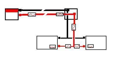
Your setup requires three main power wire fuses and one fused distribution block.

Build the box so that it performs well in the worst case scenario and, in return, it will reward you at all times.
Page of 2

  Printable version Printable version Post ReplyPost New Topic
You cannot post new topics in this forum
You cannot reply to topics in this forum
You cannot delete your posts in this forum
You cannot edit your posts in this forum
You cannot create polls in this forum
You cannot vote in polls in this forum

  •  
Search the12volt.com
Follow the12volt.com Follow the12volt.com on Facebook
Thursday, May 9, 2024 • Copyright © 1999-2024 the12volt.com, All Rights Reserved Privacy Policy & Use of Cookies
Disclaimer: *All information on this site ( the12volt.com ) is provided "as is" without any warranty of any kind, either expressed or implied, including but not limited to fitness for a particular use. Any user assumes the entire risk as to the accuracy and use of this information. Please verify all wire colors and diagrams before applying any information.

Secured by Sectigo
the12volt.com spacer
Support the12volt.com
Top
the12volt.com spacer