the12volt.com spacer
icon

New Member, site to buy components?


Post ReplyPost New Topic
< Prev Topic Next Topic >
DYohn 
Moderator - Posts: 10,741
Moderator spaceThis member has made a donation to the12volt.com. Click here for more info.spaceThis member has been recognized as an authority in Electrical Theory. Click here for more info.spaceThis member has been recognized as an authority in Mobile Audio and Video. Click here for more info.spacespace
Joined: April 22, 2003
Location: Arizona, United States
Posted: May 11, 2006 at 8:28 AM / IP Logged  

saturnsubohio wrote:
the sensitivity is exactly 2dB @ 1W/m apart.
91 Woofer/89 Tweet respecitively.
im going to have to add a "pad" on the tweeter to reduce it to a 4ohm Req. it is an 8 ohm tweeter i want to have a 2 ohm load @ the amp for 100 W.
Anything wrong with this? i couldnt think that there was except finding a decent sized resistor? or does that not even matter?

First the impedance.  No, you are not correct.  You do NOT want to try and change the impedance of any of your speakers.  Your chosen tweeter is an 8 ohms unit.  Your amplifier will be loaded by the woofer @ 4 ohms below the crossover frequency and by the tweeter @ 8 ohms above the crossover frequency.  This is how a crossover works, the speakers are not in parallel.  Do not suffer from the typical car audio misconception about seeking maximum power.  Ignore it.  You will be fine.  This is normal.

The purpose of a pad in a crossover is to match the sensitivity of the speakers.  The speakers you've chosen should work really well together without need for any pad.  The Peerless woofer is rated @ 91db, but this is at 2.83 volts into its 4-ohm impedance.  To convert that into a standard 1W/1m rating, subtract 3db so the actual rating is 88db.  The tweet you've chosen is 89db @ 1W/1m.  These ratings in effect match.

Good info from Steve above, and thanks for posting your pictures!

Support the12volt.com
saturnsubohio 
Copper - Posts: 114
Copper spaceThis member has made a donation to the12volt.com. Click here for more info.spacespace
Joined: May 21, 2004
Location: United States
Posted: May 11, 2006 at 8:53 AM / IP Logged  
you gotta love this site for info and pics like that.
i too was intrigued by the rating on the peerless woofer, i was unsure of the 2.83 volts @ 4ohm rating.. as i thought the 1W/1m rating was a "standard"
i suppose that in building my own X-over i would want to have the cleanest (minimized THD) throughout. altho im slightly confused about how the speakers are not in parallel, however i will take up that with one of my EE Professors, as we recently (read: a couple days) covered Passive filters, so he should be a good source.
Thanks again guys i really cant even begin to describe how much i've learned from this thread.
I hope i can return as much knowledge at some point in my tenure here.
2006 WRX STI
Electrical Engineer
Ohio University Alumni
DYohn 
Moderator - Posts: 10,741
Moderator spaceThis member has made a donation to the12volt.com. Click here for more info.spaceThis member has been recognized as an authority in Electrical Theory. Click here for more info.spaceThis member has been recognized as an authority in Mobile Audio and Video. Click here for more info.spacespace
Joined: April 22, 2003
Location: Arizona, United States
Posted: May 11, 2006 at 9:11 AM / IP Logged  

OK, actually the speakers ARE electrically in parallel, it's just the only time both are receiving a signal is in the crossover transition band.  As frequency rises, the woofer signal is being attenuated and the tweeter signal is increasing (in your case at 12db/octave) so the net impedance placed on the amp will never drop to what the two speakers would net in parallel.  Does that make sense?

2.83 volts = 1 watt @ 8-ohms.  2.83V = 2W @ 4-ohms.  The sensitivity difference between 1W and 2W = 3db.

Support the12volt.com
saturnsubohio 
Copper - Posts: 114
Copper spaceThis member has made a donation to the12volt.com. Click here for more info.spacespace
Joined: May 21, 2004
Location: United States
Posted: May 11, 2006 at 10:19 AM / IP Logged  
DYohn wrote:

OK, actually the speakers ARE electrically in parallel, it's just the only time both are receiving a signal is in the crossover transition band. As frequency rises, the woofer signal is being attenuated and the tweeter signal is increasing (in your case at 12db/octave) so the net impedance placed on the amp will never drop to what the two speakers would net in parallel. Does that make sense?

2.83 volts = 1 watt @ 8-ohms. 2.83V = 2W @ 4-ohms. The sensitivity difference between 1W and 2W = 3db.

yes that makes sense (although i thought alot of this made sense b4 talking to you guys).. as the Frequency rises the attenuation of the woofer is increased @ 12dB per decade above the cutoff... so shortly after cutoff the Woofer is attenuated to 94%...
is there any correlation to the fact that the impedance of a capacitor and inductor changes as Frequency increases?
impedance for a cap is [1/j(2*Pi*f)(C)]
impedance for a cap is j*(2*Pi*f)*L
so as the frequency increases the impedance of the overall circuit increases? yes,no or doesnt matter your just babbling.
im curious tho, at a frequency of say 3200Hz, the woofer is being attenuated and the tweeter is going strong.. what is the Load seen by the amp?
2006 WRX STI
Electrical Engineer
Ohio University Alumni
stevdart 
Platinum - Posts: 5,816
Platinum spaceThis member has made a donation to the12volt.com. Click here for more info.spaceThis member has been recognized as an authority in Mobile Audio and Video. Click here for more info.spaceThis member consistently provides reliable informationspace
Joined: January 24, 2004
Location: Pennsylvania, United States
Posted: May 11, 2006 at 10:34 AM / IP Logged  

You meant to say "coil" for that second formula, but speaking for myself, there are things in audio that I will gladly let stay above my head where they belong.  Those formulae are two of them.  New Member, site to buy components? - Page 5 -- posted image.

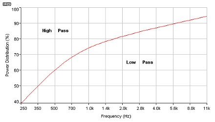
This chart from Rod Eliott's site may be of some help:

New Member, site to buy components? - Page 5 -- posted image.

Use the crossover freq and the crossover orders that you have selected along with this chart to find percentage of power to each driver.  You may be starting to worry a bit too much about the varying impedance load...just my impression.   But then, that is an area my brain was not meant to get into.

Build the box so that it performs well in the worst case scenario and, in return, it will reward you at all times.
DYohn 
Moderator - Posts: 10,741
Moderator spaceThis member has made a donation to the12volt.com. Click here for more info.spaceThis member has been recognized as an authority in Electrical Theory. Click here for more info.spaceThis member has been recognized as an authority in Mobile Audio and Video. Click here for more info.spacespace
Joined: April 22, 2003
Location: Arizona, United States
Posted: May 11, 2006 at 10:37 AM / IP Logged  
You have it.  The impedance characteristics of capacitors and inductors is why a crossover (or any other LRC circuit) works.  At very low frequencies the reactive component added by the woofer's series inductor adds essentially zero impedance (it adds its DCR) and the full signal is being utilized by the woofer.  As frequency rises the inductor adds impedance to the circuit and cuts the signal going to the woofer.  The "resistance" of the low-pass circuit goes way up after the crossover knee (there is no actual "cutoff' in a passive crossover) at a rate determined by the crossover circuit topology (in a 2nd order, at 12db/octave.)  At the same time, the reactive component of the series capacitor, which adds very high impedance at low frequencies, starts to reduce as frequency increases until after the high-pass knee, it is essentially zero (it adds its ESR) and the full signal is being utilized by the tweeter.  The load "seen" at the amp at any point in the frequency spectrum is the impedance of whichever speaker is active at that frequency.  During the crossover transition, it is a complex equation including both speakers and the reactive functions of the circuit, but a properly designed crossover will not allow the net impedance to drop significantly below the lowest speaker impedance.
Support the12volt.com
saturnsubohio 
Copper - Posts: 114
Copper spaceThis member has made a donation to the12volt.com. Click here for more info.spacespace
Joined: May 21, 2004
Location: United States
Posted: May 11, 2006 at 11:39 AM / IP Logged  
tons of great info for me there.
DYohn, i was pretty much on the right track i just dont know how to express it in english...
by what you have said in total above.
when the capacitor and coil's impedances will approach the ideal value of a parallel combination of the two? so in theory there will be max power @ the crossover knee? due to there being no inductive/capacitive(reactive) component of the impedance.
so @ 2400 Hz there should be max power dissipated across both speakers? or will there be an even 50-50 split between the amount of power.
Stevdart: yes i am intentionally making this more complex in my brain because im trying to learn the theory so i can better apply it both in the class room and the shop. That is a good graph although it looks backwords? @ a higher frequency it appears that the "high pass" is getting less power.. but thats just how it looks to me.
2006 WRX STI
Electrical Engineer
Ohio University Alumni
stevdart 
Platinum - Posts: 5,816
Platinum spaceThis member has made a donation to the12volt.com. Click here for more info.spaceThis member has been recognized as an authority in Mobile Audio and Video. Click here for more info.spaceThis member consistently provides reliable informationspace
Joined: January 24, 2004
Location: Pennsylvania, United States
Posted: May 11, 2006 at 11:55 AM / IP Logged  

That's correct.  That's why a tweeter isn't getting 100 watts at 4000 Hz.  It'll probably never get more than 10 watts of power.  The more that the frequency spectrum relies on the tweeter to produce the primary sound, the more power goes to the woofer and the less to the tweeter.  That's where the "robbing" of power due to the coils etc. come into play because of their impedance ( I think...heh heh).

er, at least I mean to say that the chart is correct.  Use it to see that at 2400 Hz the power is NOT split 50/50.

edit to add:  IIRC, this chart was used so that you can have some help in determining power values of resistors used at the various frequencies.  This showed that in most cases a 5 watt resistor is fine for the tweeter, if I remember Rod's words correctly.  http://sound.westhost.com/lr-passive.htm#7.0

Build the box so that it performs well in the worst case scenario and, in return, it will reward you at all times.
saturnsubohio 
Copper - Posts: 114
Copper spaceThis member has made a donation to the12volt.com. Click here for more info.spacespace
Joined: May 21, 2004
Location: United States
Posted: May 11, 2006 at 12:53 PM / IP Logged  
That mans description of the inductor scares me a lil, what is his reasoning that it is the worst type of passive crossover.
either way i'd say im pretty well set then in my design, i just need to wait for some $$$ to show up because to be honest i didnt plan on spending 40+ on the X-Over network.
but im happy spending it for the sound i should be getting.
Any other last minute thoughts regarding inductors?
also DYohn: where did you come up with your values for the tweeter network?
StevDart: why does this network which looks identical to what i want to accomplish has so many different components than what i had planned.
New Member, site to buy components? - Page 5 -- posted image.
2006 WRX STI
Electrical Engineer
Ohio University Alumni
DYohn 
Moderator - Posts: 10,741
Moderator spaceThis member has made a donation to the12volt.com. Click here for more info.spaceThis member has been recognized as an authority in Electrical Theory. Click here for more info.spaceThis member has been recognized as an authority in Mobile Audio and Video. Click here for more info.spacespace
Joined: April 22, 2003
Location: Arizona, United States
Posted: May 11, 2006 at 1:41 PM / IP Logged  

Again, don't concern yourself with power utilization.  As long as your woofer and all the crossover components are rated to handle the power output from your amplifier, you are OK.  As far as the tweeter is concerned, like Steve mentioned most tweeters never see more than 8-12 watts no matter what because of the frequencies they reproduce.  There is NO point in your system where "amplifier power is shared 50/50" by the two speakers.  It will never happen, nor do you want it to happen (as you would blow your tweeter.)

Power utilization as a function of frequency is what Rob's chart that Steve posted illustrated.  If you look at that chart, 80% of the amplifier's power goes into reproducing frequencies below 2KHz.  Also, don't worry about Rob Elliot being down on inductors.  While what he says is true, he tends to exaggerate the importance of some things to reinforce his own personal biases (in this case, his bias towards preferring active filters VS passive crossovers.)

The component values I listed are standard textbook values for a Butterworth 2nd order filter @ 2400Hz into an 8-ohm tweeter.

The network you posted includes Zobel circuits for the speakers, which you will not need to concern yourself with.  It is also a crossover for two 8-ohm speakers: you are using one 8-ohm and one 4-ohm.

Support the12volt.com
Page of 6

  Printable version Printable version Post ReplyPost New Topic
You cannot post new topics in this forum
You cannot reply to topics in this forum
You cannot delete your posts in this forum
You cannot edit your posts in this forum
You cannot create polls in this forum
You cannot vote in polls in this forum

  •  
Search the12volt.com
Follow the12volt.com Follow the12volt.com on Facebook
Tuesday, May 21, 2024 • Copyright © 1999-2024 the12volt.com, All Rights Reserved Privacy Policy & Use of Cookies
Disclaimer: *All information on this site ( the12volt.com ) is provided "as is" without any warranty of any kind, either expressed or implied, including but not limited to fitness for a particular use. Any user assumes the entire risk as to the accuracy and use of this information. Please verify all wire colors and diagrams before applying any information.

Secured by Sectigo
the12volt.com spacer
Support the12volt.com
Top
the12volt.com spacer