the12volt.com spacer
icon

2000 Protege door locks. Am I stupid?


Post ReplyPost New Topic
< Prev Topic Next Topic >
Stainless 
Member - Posts: 8
Member spacespace
Joined: May 08, 2003
Posted: October 10, 2006 at 12:04 AM / IP Logged  
Hey,
Working on an AutoPage RS-620 starter install in my 2000 Protege LX with the one-wire lock/unlock trigger.
I keep seeing posts that recommend using one relay for lock and one for unlock with a resistor on the ground output of the unlock relay. Fair enough, it would obviously work that way.
But, why the relays at all? Could I not just use blocking diodes on each lock/unlock wire to isolate them from each other, and plunk a resistor on the unlock wire before tying the two together into the factory lock/unlock trigger wire? The factory trigger wants a negative pulse, which the starter provides, and blocking diodes on each wire from the starter would keep current from flowing back into the starter over the non-active lock/unlock wire, no?
Here is a very quickly drawn GIF of what I mean: GIF here
Am I missing something really obvious here?
Thanks!
cntrylvr79 
Silver - Posts: 582
Silver spacespace
Joined: July 02, 2005
Location: United States
Posted: October 10, 2006 at 1:11 AM / IP Logged  
I don't see why that wouldn't work.  THe only reason you might have to use the relays is if the unit doesn't provide enough current to trigger the locks.
Cause I'm So white and nerdy...
First Class Certi-fried installer
master5 
Silver - Posts: 1,123
Silver spacespace
Joined: October 10, 2006
Location: United States
Posted: October 10, 2006 at 1:30 AM / IP Logged  
No, you are not stupid. On most one wire doorlocks I do it exactly that way and have had no problems. The reason they state it requires relays is because most systems doorlock outputs do not provide a strong enough ground. (the opposite applies if the vehicles doorlock circuit requires positive).The resistor values given to operate the factory doorlocks take this into account so by using the relay you are "boosting" the negative doorlock output of the brain to a "true" ground. (optimally zero resistance or very close to it).The thing you need to do is figure out what value resistor(s) you are going to need to get the doorlocks to work as it will not be the same. Now I find many times that one of the outputs will work with no resistor. This is due to the fact that the resistance of the output circuit/wire is within tolerance on it's own. Assume this is the lock wire. Now for unlock you will need a resistor value different from the one reccomended. I usually start about 500-1000 ohms lower and experiment from there. Typically I get it within 2 or 3 tries max but occasionally hit the jackpot first attempt. Don't worry about experimenting with resistor values as it won't damage anything. The doorlocks simply will not operate until you are within tolerance. And yes, do not forget to diode isolate. If the doorlocks are negative make sure the stripes (cathode) are toward the brain. If the doorlocks are positive point the stripes away from the brain. One thing to note, if the particular system you are installing has internal doorlock relays you can simply use the resistor values given as the output will be "true" ground or 12volt positive if needed. Good Luck.
BulletTooth 
Copper - Posts: 122
Copper spacespace
Joined: December 13, 2002
Location: United States
Posted: October 10, 2006 at 3:01 AM / IP Logged  
Simply said the alarms brain has internal resistance so if you're connecting 1K resistor to the door lock, then the car actually sees 1K + alarms internal resistance = wrong value = no lock. When you use relays or the alarm has built in relays then you are sending the proper signal.
Stainless 
Member - Posts: 8
Member spacespace
Joined: May 08, 2003
Posted: October 10, 2006 at 11:29 AM / IP Logged  
Hey again,
Thanks for all the responses so far. I had thought of the possibility that the starter's lock/unlock output wouldn't be enough to trigger the factory relays, but the factory trigger wire is tiny (20 gauge or smaller) and really doesn't look like any kind of high-current affair, so I hope this isn't a problem.
The starter's internal resistance is a good point. I'll monkey around with it and post my results if anyone would find it useful information.
Thanks again.
sparkie 
Platinum - Posts: 2,061
Platinum spacespace
Joined: November 06, 2003
Location: Canada
Posted: October 10, 2006 at 2:15 PM / IP Logged  
Do yourself a favour and use relays. This is the proper way of doing it and it won't give you problems. Doing it without relays may cause it to not work at times. If you use diodes it won't work properly. Diodes add resistance. It is very simple to wire up the relays. Take it from someone who has seen many other installers make this mistake. In the time it has taken you to read these posts, the relays could be hooked up.
sparky
master5 
Silver - Posts: 1,123
Silver spacespace
Joined: October 10, 2006
Location: United States
Posted: October 10, 2006 at 9:06 PM / IP Logged  

Please understand that I am not reccomending to do it this way as a shortcut  or laziness. There is nothing wrong with using relays and it is not that difficult and doesn't take that long. However, this post asked if it could be done without relays and the answer is yes. I am MECP Master certified, hold a degree in electrical engineering and hold patent pending status on several industry related devices. I was training coordinator at a mobile electronics school for 6 years and have been a high end installer for over 15 years so believe me I know what I am doing.  first off you do not need to be concerned about the thin wires and thier current handling in this case. The doorlock wires go to a module in the vehicle and draw no more then a relay coil, perhaps less. Secondly, yes it is correct that the diode has some resistance but this resitance will not change, nor will the value of the resistor(s) you use, they are a fixed value. So someone who knows more then me PLEASE explain how this will be unreliable once you determine the resistor value required, or within it's tolerance or work any better or worse then using the relay. and if you wish to challange me on this please do so in a way that makes technical sense in the real world. I wish some poeple would have an open mind and realize that sometimes there is more then one way to do something and that doesn't mean other options are wrong or any less professional. And like I stated in my first post reply, I do it this way often and have NEVER, EVER not ONCE had a problem and I work in a very busy shop. To sum it up in a nutshell, yes you can do it with resistors and diodes OR you can use relays, both are easy and do what it is supposed to which is send a resistor value within a certain tolerance to the vehicles doorlock module.  As a side benefit the diodes and resistors have no moving parts so in reality there is more potential for a relay to develop a problem, although I have rarely seen a quality relay go bad, it does happen.

snotdobbs 
Copper - Posts: 148
Copper spacespace
Joined: September 11, 2003
Location: United States
Posted: October 10, 2006 at 9:27 PM / IP Logged  
relays are great but they are unneccesary half the time with resistive lock circuits.......the protege will lock and unlock reliably every time with diodes granted the resistance  is correct.....been there done that......oh yeah my girls car is 02 protege...so uh yeah if it didnt work id be hearing about it every morning
captainzab 
Silver - Posts: 606
Silver spaceThis member has made a donation to the12volt.com. Click here for more info.spacespace
Joined: February 09, 2005
Location: United States
Posted: October 10, 2006 at 9:36 PM / IP Logged  
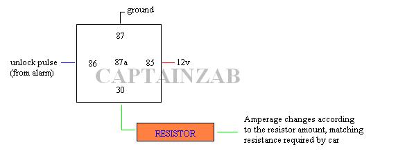
You must use the resistor after the relay output, because it requirs a full 1 amp before it can be changed by the resistor.
MOST ALARM HAS OUTPUT OF (within the range) 200mA!!! (except those with built in relay for doorlocks, which requires you to choose the input.)
If you are not adding your own relay, then most likely your alarm has the built in relay already.
2000 Protege door locks. Am I stupid? -- posted image.
Proper Way ^^^^^
autopage is like DEI in that it has a wire that sends +lock and - unlcok on the same wire, install manual doesnt specify that it is 200mA (it is though), so you must use a relay to get the proper resistance.
Ex.
200mA / resistance = small number
1A (1000mA) / resistance = big number that matches resistance required by car
Note: You Always Dont Get What You Pay For.
master5 
Silver - Posts: 1,123
Silver spacespace
Joined: October 10, 2006
Location: United States
Posted: October 10, 2006 at 10:27 PM / IP Logged  
captianzab, stainless was not asking how to do it with a relay, which is what you replied. He was asking why it couldn't be done without relays and I explained how it could be done without relays, how I have time after time sucessfully done it without relays and someone even replied with the same car that is done without relays and works reliably. As far as all the info about current here is what I find. First off you are correct, most systems outputs are rated at 200ma unless it utilizes internal relays. a relay coil draws 150ma which is fine. However, lets use ohms law, which by no means did I invent, but it is basic electronics 101. Lets say for example  lock  requires a resistance of 100 ohms. Using ohms law we can easily determine the current draw +/- the percentage of tolerance (I believe most factroy modules are pretty loose, around 20%). Regardless here is the total draw.  I = E/R    I = 12/100    I = .12a   or 120 milliamps, less then a relay. Lets say the unlock requires 1000 ohms.  I = 12/1000   I = .012a or 12milliamps.  much much less then a relay. we see here the higer the resistance the less current is used and most doorlock circuits lie within this rhelm or higher. The fact that DEI and other systems throw both negative and positive is not an issue since we are going to diode isolate the 2 wires. If we use relays of course we don't need diodes since the relays ioslote the wires for us. Need I say more?
Page of 2

  Printable version Printable version Post ReplyPost New Topic
You cannot post new topics in this forum
You cannot reply to topics in this forum
You cannot delete your posts in this forum
You cannot edit your posts in this forum
You cannot create polls in this forum
You cannot vote in polls in this forum

  •  
Search the12volt.com
Follow the12volt.com Follow the12volt.com on Facebook
Friday, May 3, 2024 • Copyright © 1999-2024 the12volt.com, All Rights Reserved Privacy Policy & Use of Cookies
Disclaimer: *All information on this site ( the12volt.com ) is provided "as is" without any warranty of any kind, either expressed or implied, including but not limited to fitness for a particular use. Any user assumes the entire risk as to the accuracy and use of this information. Please verify all wire colors and diagrams before applying any information.

Secured by Sectigo
the12volt.com spacer
Support the12volt.com
Top
the12volt.com spacer