the12volt.com spacer
icon

98 cavalier door locks


Post ReplyPost New Topic
< Prev Topic Next Topic >
djtripz 
Member - Posts: 37
Member spacespace
Joined: July 11, 2005
Posted: January 01, 2007 at 10:47 PM / IP Logged  

hey, i have read all the threads on the door locks on the 98 cavalier (without keyless entry) but i am completely mind boggled... im trying everything and im getting frustrated and i dont want to.  heres what i got...

i know the locks are 5 wire alternating... i have the light blue unlock wire, i have the white lock wire... and i have the GREEN/ black neg trigger...

heres my problem... i am having a very dificult time wiring up the relays... ive been to every post and diagram trying to explain the hook up but i am just not getting it...  heres what i need to know...

can someone please tell me which wire exactly goes where it should (ie light blue wire switch side goes to 87 in the relay.. sumthing like that)  where to put the door trigger (it says use both the GREEN/ black and light blue) but i don't know where to put them together... also.. i don't know which wire to use from the alarm module, positive door trigger or negative... i think if i had all that i could figure it out.  it would be a greattt help... this is a remote start unit prestige 996.. i havn't even tried to attmept the remote start part yet so im sure ill be back on here looking for help with that.. but if sumone can steer me in the right direction to get these locks working, that would be great.

KarTuneMan 
Platinum - Posts: 7,056
Platinum spaceThis member has made a donation to the12volt.com. Click here for more info.spaceThis member consistently provides reliable informationspace
Joined: December 14, 2004
Location: Isle Of Man
Posted: January 01, 2007 at 11:04 PM / IP Logged  
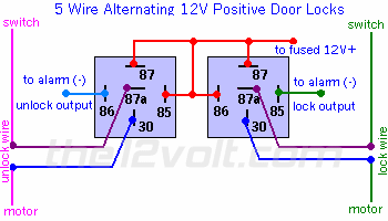
98 cavalier door locks -- posted image.
You tried THIS diagram....The switch side (as you can see) goes to 87a. to make sure you have the correct side of the wire, cut it and put you meter on it, then hit the lock or unlock switch on the PASSENGER side. If the meter reads voltage, you know you have the switch side of the wire. The other end of the cut wire goes to pin 30. On a relay pin 30, and 87a, are connected while the relay is NOT energized, this allows your factory switch to continue to work. Remember....what ever is hooked to pin 87, pin 30 will become, when the relay is energized. So if you needed to "throw" a ground, you would put pin 87 to ground.
chris354 
Silver - Posts: 253
Silver spacespace
Joined: February 19, 2005
Location: United States
Posted: January 01, 2007 at 11:10 PM / IP Logged  

lock

87 and 86 12 volt

85 neg lock output from alarm

30 motor side of blue wire

87a switch side of blue wire

unlock

87 and 86 12 volt

85 neg unlock output from alarm

30 motor side of white unlock wire

87a switch side of white unlock wire

make sure when testing for the switch side of the wire use the passenger side switch.

I would find the white wire running up the pillar with an orange wire and use it for positive door trigger so purple on alarm to white. You may have to program for delayed arming if the dome light fades out if not it should be fine.

chris354 
Silver - Posts: 253
Silver spacespace
Joined: February 19, 2005
Location: United States
Posted: January 01, 2007 at 11:12 PM / IP Logged  
Isaid pos. door trigger should be neg and go to green neg door trigger wire.
djtripz 
Member - Posts: 37
Member spacespace
Joined: July 11, 2005
Posted: January 02, 2007 at 12:55 AM / IP Logged  
thanks guys, kartune, i tried that and didn't seem to work.. chris, ill try with ur instructions and hopefully it will work.. the wire diagrams say i have to use both the blue lock wire and GREEN/ black wire for door trigger to alarm... since i cut the blue wire in half for the relay, which side do i use to run it to the alarm module??
chris354 
Silver - Posts: 253
Silver spacespace
Joined: February 19, 2005
Location: United States
Posted: January 02, 2007 at 1:42 AM / IP Logged  

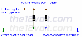
Yoo dont use the lock wire there is another wire that is the door trigger wire that is blue also. You can do it that way but have diode isolate those 2 wires.

98 cavalier door locks -- posted image.

djtripz 
Member - Posts: 37
Member spacespace
Joined: July 11, 2005
Posted: January 02, 2007 at 1:47 AM / IP Logged  
ok, thats what i plan on doing, with the diodes.. but for the passenger negative trigger... isn't it the same light blue wire  as the lock wire?  if so, since it is split to the diode, does it go on switch side or motor side? i already have all of these wires in the open, i really hate searching for more wires, so if i can use what i have that would be great.
chris354 
Silver - Posts: 253
Silver spacespace
Joined: February 19, 2005
Location: United States
Posted: January 02, 2007 at 1:58 AM / IP Logged  
It is a differant wire has nothing to do with the lock wire.

Sorry, you can NOT post a reply.
This topic is closed.

  Printable version Printable version Post ReplyPost New Topic
You cannot post new topics in this forum
You cannot reply to topics in this forum
You cannot delete your posts in this forum
You cannot edit your posts in this forum
You cannot create polls in this forum
You cannot vote in polls in this forum

  •  
Search the12volt.com
Follow the12volt.com Follow the12volt.com on Facebook
Tuesday, April 23, 2024 • Copyright © 1999-2024 the12volt.com, All Rights Reserved Privacy Policy & Use of Cookies
Disclaimer: *All information on this site ( the12volt.com ) is provided "as is" without any warranty of any kind, either expressed or implied, including but not limited to fitness for a particular use. Any user assumes the entire risk as to the accuracy and use of this information. Please verify all wire colors and diagrams before applying any information.

Secured by Sectigo
the12volt.com spacer
Support the12volt.com
Top
the12volt.com spacer