the12volt.com spacer
icon

wiring trunk pin switch to door trigger


Post ReplyPost New Topic
< Prev Topic Next Topic >
master5 
Silver - Posts: 1,123
Silver spacespace
Joined: October 10, 2006
Location: United States
Posted: February 26, 2007 at 9:21 AM / IP Logged  

Yes I have a great idea...just do what I have been suggesting all along. Using a DMM find the wire at the trunk light that shows negative 12v when the trunk is open...if you are on the correct wire it will also show 12v positive when the trunk is closed...that is normal.

Now....connect the wire from your remote start that is "Negative trigger input hood/trunk" to that wire and all will be fine. Again..I will ask that you NOT confuse this wire with the "negative shutdown" wire.

I can't make it any simpler as if you are not able to do this you really will have troubles if you start messing with diodes...well we see what happened when you did. Why don't you try it the way I am suggesting,? I just don't understand the issue here.

Best of luck, my job should be done here.

audioman2007 
Copper - Posts: 580
Copper spacespace
Joined: February 20, 2007
Location: United States
Posted: February 26, 2007 at 11:28 AM / IP Logged  
The only trigger wires I have is the negative door trigger and positive door trigger. I do have a hood pin input that acts as a trigger, but that same wire also acts as a remote turnoff, if the hood is opened during remote start.
master5 
Silver - Posts: 1,123
Silver spacespace
Joined: October 10, 2006
Location: United States
Posted: February 26, 2007 at 5:25 PM / IP Logged  

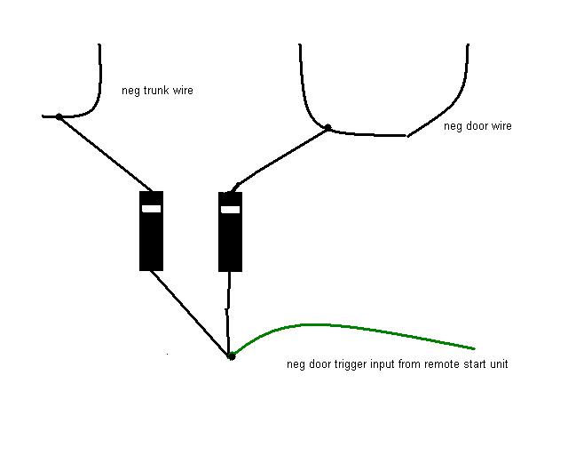
That is kinda strange..I have never seen a security system that does not give a dedicated wire to protect the trunk/hatch but perhaps it is like a K-Mart unit or something like that. But regardless it is extremely simple to use a pair of diodes to get the trunk protection by tying it into the door wire since they are both negative. If the following diagram does not work or you can't figure it out, then either get a pro to help you or live without it. This is about as basic as it gets....... good luck

wiring trunk pin switch to door trigger - Page 3 -- posted image.

audioman2007 
Copper - Posts: 580
Copper spacespace
Joined: February 20, 2007
Location: United States
Posted: February 26, 2007 at 6:19 PM / IP Logged  
Thanks for the diagram master. I totally understand it. Now my exact setup would be alittle different because I have the door trigger running to my domelight wire. But I would do the same thing as your diagram. My only question is that i had it hooked up the way you had it (running the diode wire from the negative door trigger and ran it to the ground wire that runs from the trunk light. Now I have 2 wires that run off the trunk light; a brown wire and a black (ground wire). Should I just use a DMM and see when there is 12 volt in the brown wire?
master5 
Silver - Posts: 1,123
Silver spacespace
Joined: October 10, 2006
Location: United States
Posted: February 27, 2007 at 12:41 PM / IP Logged  

Well as long as the wire shows negative when the door is OPEN..and the wire you connect to in the trunk shows a negative when the trunk is open...the diagram will have to work properly for you..do not be concerned with what the wire is called..use a DMM and all will work. The wire for the trunk light you need to tap into will also show 12v positive but ONLY when the trunk is closed. That is ok...just wire the diodes as shown to prevent back feed.

The negative input wire on your system that triggers the alarm is waiting to see a negative...when it does..the alarm cycles..thats all there is to it. When it sees positive or nothing it does nothing.

Page of 3

Sorry, you can NOT post a reply.
This topic is closed.

  Printable version Printable version Post ReplyPost New Topic
You cannot post new topics in this forum
You cannot reply to topics in this forum
You cannot delete your posts in this forum
You cannot edit your posts in this forum
You cannot create polls in this forum
You cannot vote in polls in this forum

  •  
Search the12volt.com
Follow the12volt.com Follow the12volt.com on Facebook
Thursday, April 18, 2024 • Copyright © 1999-2024 the12volt.com, All Rights Reserved Privacy Policy & Use of Cookies
Disclaimer: *All information on this site ( the12volt.com ) is provided "as is" without any warranty of any kind, either expressed or implied, including but not limited to fitness for a particular use. Any user assumes the entire risk as to the accuracy and use of this information. Please verify all wire colors and diagrams before applying any information.

Secured by Sectigo
the12volt.com spacer
Support the12volt.com
Top
the12volt.com spacer