


trying to control linear actuators


Posted: April 06, 2007 at 12:59 PM / IP Logged
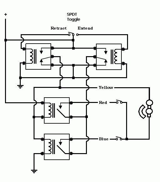
 This assumes the microswitch is set up to be in the Normally Open position when the limit is reached, and NC otherwise.changed the ground control for the relays to use the opposing side relay to prevent a situation where both relays can get energized if the control is hit while already moving, stopping the motor from traveling to the limits.
Posted: April 07, 2007 at 2:29 AM / IP Logged

Posted: April 09, 2007 at 9:48 AM / IP Logged
Posted: April 09, 2007 at 10:20 AM / IP Logged
Posted: April 09, 2007 at 7:14 PM / IP Logged
Sorry, you can NOT post a reply.
This topic is closed.
 Printable version
| You cannot post new topics in this forum You cannot reply to topics in this forum You cannot delete your posts in this forum You cannot edit your posts in this forum You cannot create polls in this forum You cannot vote in polls in this forum |

| Search the12volt.com |
Follow the12volt.com 
Monday, April 20, 2026 • Copyright © 1999-2026 the12volt.com, All Rights Reserved • Privacy Policy & Use of Cookies

Monday, April 20, 2026 • Copyright © 1999-2026 the12volt.com, All Rights Reserved • Privacy Policy & Use of Cookies
Disclaimer:
*All information on this site ( the12volt.com ) is provided "as is" without any warranty of any kind, either expressed or implied, including but not limited to fitness for a particular use. Any user assumes the entire risk as to the accuracy and use of this information. Please
verify all wire colors and diagrams before applying any information.
