


creating circuit for multi in single out
Home /
the12volt's Install Bay /
General Discussion / creating circuit for multi in single out ( Topic Closed)


Posted: February 28, 2007 at 6:52 PM / IP Logged


Posted: February 28, 2007 at 10:45 PM / IP Logged
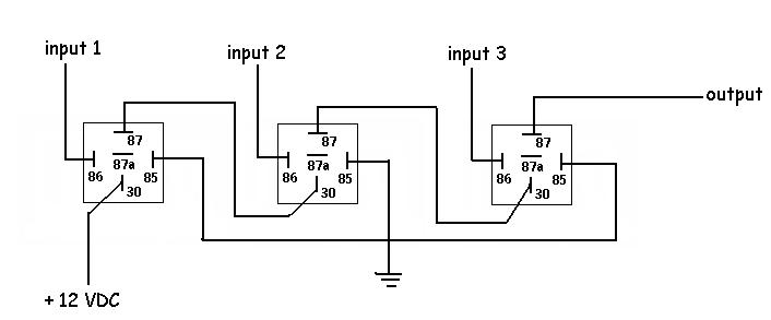 The output will only be on if all three inputs are on, and the inputs are all 12VDC.
Posted: February 28, 2007 at 11:36 PM / IP Logged
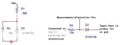 The other way would be to use CMOS logic chips, they are capable of source voltages up to 18v, the main problem is that they are extremely sensitive to static electricity so you will need to design around that downfall. I don't know what to do to eliminate this problem so pursuing this idea is up to you.
Sorry, you can NOT post a reply.
This topic is closed.
 Printable version
| You cannot post new topics in this forum You cannot reply to topics in this forum You cannot delete your posts in this forum You cannot edit your posts in this forum You cannot create polls in this forum You cannot vote in polls in this forum |

| Search the12volt.com |
Follow the12volt.com 
Thursday, May 14, 2026 • Copyright © 1999-2026 the12volt.com, All Rights Reserved • Privacy Policy & Use of Cookies

Thursday, May 14, 2026 • Copyright © 1999-2026 the12volt.com, All Rights Reserved • Privacy Policy & Use of Cookies
Disclaimer:
*All information on this site ( the12volt.com ) is provided "as is" without any warranty of any kind, either expressed or implied, including but not limited to fitness for a particular use. Any user assumes the entire risk as to the accuracy and use of this information. Please
verify all wire colors and diagrams before applying any information.
