This is truly one of my favorite topics. There are actually several acoustic phenomenon happening all at the same time. You can break these down into groups prioritized by the expected percentage of effect that each will have on the total transfer function.
1. Space loading. Space loading is when sound reflects off a solid surface and amplifies its self in the process. This effect increases as frequency drops and is the prominent reason for the large boost in bass in cars. The predicted in car response that most box programs generate for you use this and only this to predict transfer function. This alone will not give you an accurate prediction with in 12db.You can find out more about this here http://www.trueaudio.com/st_spcs1.htm
2. The second is due to standing waves. There are multiple standing waves in the interior of a vehicle do to the many parallel solid and semi solid reflective surfaces. Check out this video of an experiment that shows how standing waves are frequency dependant and become more complex as frequency rises. http://www.youtube.com/jp.swf?video_id=Zkox6niJ1Wc&eurl=http%3A//en.wikipedia.org/wiki/Standing_wave&iurl=http%3A//img.youtube.com/vi/Zkox6niJ1Wc/2.jpg&t=OEgsToPDskKC1Ua75Pj7BZMCFHMC35jD&autoplay=1. Notice how the effect is always more drastic near the perimeter of the acoustical area. This is why standing waves in a vehicle are so important. Due to the close proximity of your head to a wall at all times in a car the effect is dramatic.
3. The next is diaphragmatic absorbers. There are many surfaces within a car that will act as an acoustic reflector at certain frequencies and as an absorber at others. This is aggravated by the presence of standing waves at frequencies that over lap these points. One way to battle this is to reduce the gain at the problem frequency in only one channel in a stereo situation. This can actually cause an acoustic gain from the listening position due to the standing wave null physically shifting away from the listening position. This is why Audiocontrol EQs have discrete L and R adjustments.
4. The next is multiple resonant chambers interacting with each other causing new standing wave formations as well that I like to call third party resonances. This is where for example the trunk resonates at one frequency but also resonates at a second frequency when combined with the resonant frequency of the passenger compartment. I know of no accurate way of predicting this in the car environment. In loudspeaker design I deal with this all the time. For example a speaker has a resonant frequency and the enclosure has a resonant frequency and when combined this produces a new resonant frequency. Due to the well documented attributes of enclosure building materials and construction this is not nearly as difficult to predict with in an enclosure. Vented enclosures are a prime example of how this effect can be advantageous. Though this can not be accurately predicted before hand, knowing about it and being able to identify the phenomenon while performing a transfer function test will enable you to take advantage of the phenomenon rather than fall victim to phenomenon.
I have barely scratched the surface of this topic here. There is simply not enough room, but I hope that I have led you to the information that you seek.
There is however a rather simple and scientific solution to a cars low frequency acoustic environment. If you own a computer and a cheap computer microphone you can test your cars transfer function for free and then attempt to either reverse engineer the situation to better understand it or you can take that info at face value and design a sub box taking that information into account. Once you have your vehicles transfer function in hand you can import that info into a program like bass box pro or leap enclosure shop and then see how various box designs with various tuning frequencies will interact with your vehicle.
So whats the answer to how do you find the right frequency to tune your box to after understanding your vehicles transfer function? This involves becoming familiar with what frequency response curves, cone displacement curves, and group delay curves will get you what you are looking for. I will try to comment on this in future posts but dont have the time now. But its really not that complex compared to the rest of this.
To test your vehicles transfer function download OscilloMeter 4.14(free) or pay for TrueRTA $39.95 (better- way more user friendly). Using this software and a regular mic you can send a pink noise (the free version of TrueRTA comes with a good pink noise generator that you can pipe into your system) signal to your amps and use your cheap mic to sample the out put of your sub(s).
First run a long wire from your sub amp to your sub and place your sub on the ground out side of your car. Then place your microphone 2 meters from your sub and place it on the ground pointing towards your sub.
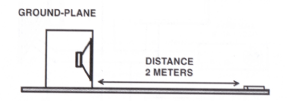
Find a relatively empty and noise free parking lot (no traffic or people) with no buildings or large surfaces within 30 ft. I show up to work early before anyone ells and place the sub box near the corner of my shop (I cant get 30 ft. from a building). Placing the box at the corner drastically reduces any reflections that the building can send back to my mic. At 30hz any surface within 37.69 ft. of the sub will color your results by at least 6db and that gets even worst as frequency goes down so dont under estimate the reflections. In this test the ground acts like a reflector and will boost your results by 6 db. Thats the reason why we place the mic 2 meters away. Sound pressure drops 6 db at every doubling of distance so this is the equivalent of placing the sub 1 meter from the mic in the car. When we test in the car we want the mic positioned where we sit. If this is more les than 1 meter we adjust the results by X db using the formula that sound decreases by 6 db for every doubling of distance and our reference distance is 1 meter. The short cut way of doing this is to ignore it. A sub in a car is usually more than 2 meters from the listener and we are more concerned with larger effects on frequency response to the tune of 12 db. This sensitivity information is only for reference and may be quite useful to you in the future. I reiterate dont under estimate the effects of reflections in your test.
Now you have to record the amplitude of every frequency at every 1/3 octave. Keep in mind that cheap mics have low SPL limits. If you exceed the limitations of your mic all test results will be useless. The reason why we dont need expensive calibrated equipment for this test is that its all relative. You are simply testing the difference in sensitivity (every1/3 octave) at the output of your sub first outside of the car and then inside of the car. And then importing that information into a program like bass box or leap. I dont know if win ISD is capable of that. If anyone knows for sure I would like to know. You dont need to worry about calibrating your sound card or your mic for this test. You dont have to worry about if your mic is weighted for this test. Once you have completed this test outside of the car and then from the listening position of the car you can subtract the outside test from the in car test and you will have the transfer function. If you are going to even entertain the idea of this test You will probably need more info than I have stated here. Feel free to ask. I never learned trig and never graduated high school so I envy your education. I would be honored to assist in any way.
You are not likely to find all of the information required to accurately describe the acoustical environment in a vehicle in a single location. The reason for that is some what complex but in short the educated and experienced engineers that could potentially understand the answers to this either have little interest and experience in the subject as it pertains to cars or simply have bigger fish to fry.


 Topic Closed)


 This should be one part of the whole formula in finding your resonant frequency. There is an easier and more straight forward real world method that doesn't require a bunch of formula's. The formula's are just so cool though! lol. The formula you were using was n * v / 2 * L. The "n" stands for the resonant frequency frequency that you which to obtain. If you plug one into the "n" variable, then you will obtian the fundamental frequency, two while obtain the 1st overtone, three will obtain the second overtone, and so on. "v" is the speed of sound. Different temperatures will equate different velocities for the speed of sound. "L" is the length you are trying to determine a resonant frequency for. That equation takes the order of the frequency that you are trying to find, in your case the 1st fundamental frequency, which is 62.5 Hz, and determines the frequency. Not very useful alone, but if you were to find enough of these throughout your vehicle and matched the wave coming out of your enclosure to that resonant frequency and controlled that wave so that it would follow that path until it reached the point in which it was to be measured, then, theoretically, it should boost your SPL.The more realistic method is to forget about the physics of it all and just use a meter and sine waves to test the actual SPL at different points. To do this, play several different, individual sine waves. Set the meter whereever you need the system to be the loudest. Find the loudest frequency in that location. Next, play the sine wave that you determined to be the loudest and move your enclosure into different positions to determine the loudest one for the location you are testing. Finally, retest for your loudest frequency and change it if another one took its place. You can use programs, such as WinISD, to build an enclosure that will maximize your vehicle's resonant frequency.I've known about that method for a while now, but I decided to give your method a try. I knew that the one resonant frequency alone wouldn't do you any good, but I wondered if I might accurately determine my own using the formulas when I worked enough of the resonant points up. Maybe when I understand the nature of waves better...lol. My resonant frequency, for the fundamental, came out to be 101 Hz. I know my resonant frequency to be 70 Hz. So, that one resonant frequency alone isn't enough. You need to calculate alot of different paths.
 Printable version


