the12volt.com spacer
icon

cm4200, 94 taurus door trigger


Post ReplyPost New Topic
< Prev Topic Next Topic >
showagon 
Member - Posts: 9
Member spacespace
Joined: November 25, 2007
Posted: November 27, 2007 at 5:18 PM / IP Logged  
noo, in my little tests i did not hit the brake because i didn't really know what was going on, i just tried that and i got controll of my car back, so i suppose it all works well, thanks again.
however the remote start was just sort of a bonus to the remote entry i really wanted that i cannot get to work. my realays won't flip and i've now gone through 2 different kinds, the one i have now that i thought would of been bomproof is this one: http://www.partsexpress.com/pe/pshowdetl.cfm?Partnumber=330-070 except it's the actual bosch version.
i have tried it on the horn output both lock/unlock and trunk release outputs, i hooked up the 2 feet that are suposed to controll the coil (one wire the (-) 200ma trigger and the other (+)12V) i even flipped them around incase it had a diode in it. i also had my voltmeter on continuity hooked up to 30 and 87a so i could tell if it flipped if for soem reason it didn't go click. so grrrr i dunno what to do now, i woudl rather like to complete the whole installation myself.
moonliter 
Copper - Posts: 322
Copper spacespace
Joined: February 28, 2007
Location: Canada
Posted: November 27, 2007 at 5:49 PM / IP Logged  

Is your taurus a 2 doors or 4 doors ? how many power lock switches does it have ? this will help me to figure out what you need.

showagon 
Member - Posts: 9
Member spacespace
Joined: November 25, 2007
Posted: November 27, 2007 at 6:08 PM / IP Logged  
it is a wagon, so 4 doors have power lock, but only driver and passenger have switches. and the tailgate of course is on its own thing. how does this solve the mystery of my relays themselves not doing anything? or are you getting to that?
thanks again for all your help, the remote start works 100% so far i can tell, all the safty bits do their job to.
moonliter 
Copper - Posts: 322
Copper spacespace
Joined: February 28, 2007
Location: Canada
Posted: November 27, 2007 at 7:06 PM / IP Logged  

For your doorlocks to work, use following diagram, connect the blue wire on cn4 to pin 86 of the left relay, blue/black wire on cn4 to pin 85 of the right relay. Connected red lined of the diagram to a fused 12v+.

At driver kick panel, find the unlock wire (pink/lt.green) tested (12v+) when you press the unlock button on the door. Lock wire (pink / YELLOW) tested (12v+) when you press the lock button on the door.

Clip these 2 wires and retest again with your dmm with red lead on unlock wire and the black lead on lock wire. The tests should show (+12v) when unlock button is pressed and (-12v) when lock button is pressed. When you confirm the test then these are your unlock and lock wires for the switch side.

Connect the switch side unlock wire to 87a of the left relay and the car side of the unlock wire to 30 of same relay. Connect the switch side lock wire to 87a of the right relay and the car side of the lock wire to 30 of right relay.

          cm4200, 94 taurus door trigger - Page 2 -- posted image.

showagon 
Member - Posts: 9
Member spacespace
Joined: November 25, 2007
Posted: November 28, 2007 at 11:38 AM / IP Logged  
hmmm, ok i will hold on to this good thing too casue i would of wired it all wrong, my problem is though that off the trigger lines of the brain i can't get a relay to flip, like they go *click* when you run the power through them, i even took one apart to understand 100% how it works and so i could watch it. i only have 1 of the good bosch ones so i would like to get that to work before i get more (they were $12 each!) so i was trying it on my horn last night and it wouldn't flip, here's how i wired it:
cm4200, 94 taurus door trigger - Page 2 -- posted image.
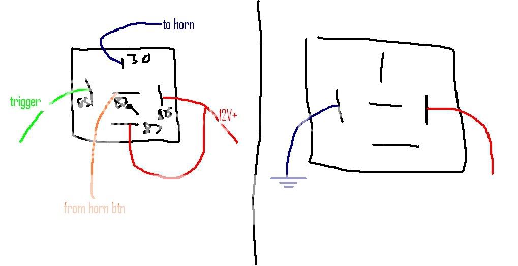
the only way i can get it to click is if i use the 12 V and ground the other side (pic on right)
moonliter 
Copper - Posts: 322
Copper spacespace
Joined: February 28, 2007
Location: Canada
Posted: November 28, 2007 at 12:56 PM / IP Logged  
I couldn't understand why it was connected that way ( left diagram ). your horn is neg trigger yellow/lt.green @ steering column harness. just connect the white wire @ cn2 - 7 to the yellow/lt.green horn wire. To test the horn, press & hold lock button for 3.5 seconds. or press lock button for 1/2 sec. Check remote button functions 8, make sure horn function is turned on. Also cn2 harness is firmly plugged in.
showagon 
Member - Posts: 9
Member spacespace
Joined: November 25, 2007
Posted: November 29, 2007 at 12:14 AM / IP Logged  
hmmmm, again i screwed up, i thought i had tried that earlier and go nothing so i was trying relays, but now i have direct connected it again and now my horn works.
anyway i think i am about to get out the problem i've been trying to get out through my other questions that were wrong. here is my picture:
cm4200, 94 taurus door trigger - Page 2 -- posted image.
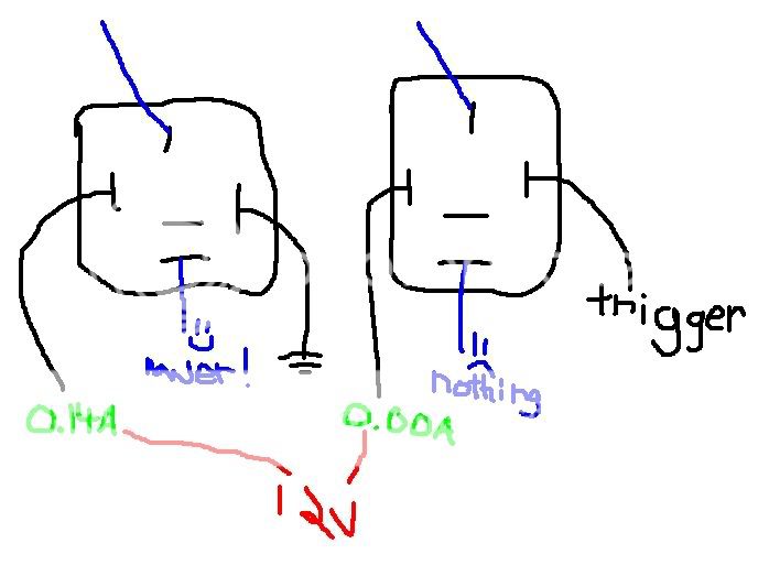
so when i use power and ground (left) i get 0.14A showing on my meter (in the 10A unfused position) and the switch flips, however when i try to use one of the negative triggers from the brain i get the picture on the right. nothing happens and no switch flipping occurs. i have tried the door lock, unlock and trunk triggers. i have also tried putting the meter on the trigger side of the relay and get the same reading.
tomorrow i will get another of the good bosch relays and wire up the door lock picture posted.
i am just puzzled as to why i can't get the things to flip by themselves.
moonliter 
Copper - Posts: 322
Copper spacespace
Joined: February 28, 2007
Location: Canada
Posted: November 29, 2007 at 4:36 PM / IP Logged  
If you already tried connecting the lock, unlock or truck neg output on cn4 to pin 85 of the bosch relay and (+12v) to pin 86. when you press respective button and relay wouldn't pull in. It is almost safe to say that the neg outputs on the brain were fried.
Page of 2

Sorry, you can NOT post a reply.
This topic is closed.

  Printable version Printable version Post ReplyPost New Topic
You cannot post new topics in this forum
You cannot reply to topics in this forum
You cannot delete your posts in this forum
You cannot edit your posts in this forum
You cannot create polls in this forum
You cannot vote in polls in this forum

  •  
Search the12volt.com
Follow the12volt.com Follow the12volt.com on Facebook
Friday, May 17, 2024 • Copyright © 1999-2024 the12volt.com, All Rights Reserved Privacy Policy & Use of Cookies
Disclaimer: *All information on this site ( the12volt.com ) is provided "as is" without any warranty of any kind, either expressed or implied, including but not limited to fitness for a particular use. Any user assumes the entire risk as to the accuracy and use of this information. Please verify all wire colors and diagrams before applying any information.

Secured by Sectigo
the12volt.com spacer
Support the12volt.com
Top
the12volt.com spacer